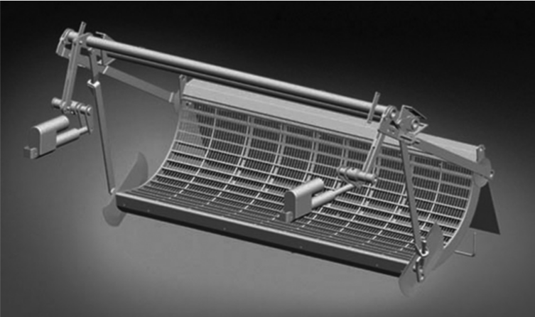
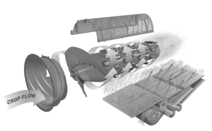
Following the gathering procedure, threshing process takes place, and is considered the most important operational task of the entire working chain of combine harvesters. The threshing process refers to the detachment of grain from its flowery cover. This task is achieved thanks to the suitable space adjustment between the combine concave and the cylinder (the clearance).
How can this interaction bring about the successful performance of threshing process? And how is the threshing unit of a combine harvester composed of? Understanding clearly about this critical operation of combine harvester shall enable you to maximize your performance efficiency. Everything about the threshing unit and its working mechanism will be answered in our following article.
Function of Threshing unit
After the grain collecting task comes the threshing process, which contains the detachment of grain from its flowery cover (such as ears, pods, panicles, etc.) until they can move freely. The threshing process, being the second phase in a combine harvester’s working process, is executed thanks to the centrifugal forces and friction generated through a mechanical operation, as well as friction among different parts of the ears.
Following closely after the threshing section is the grain separation procedure. During the latter procedure, grain is migrated freely through the MOG mixture, accompanied by their directed passage through the openings of a separating metallic surface. These series of operations happen in the threshing unit or a chain of many threshing units with diverse sizes and designs.
Regarding the structure of threshing and separating units, they comprise a rotating cylinder (or rotor), attached with moving parts such as rasp bars and a separating body called the cage or concave. Such combine concave conveys the impact forces onto the crop plants which are fed into the threshing space. Ultimately, the crop plants are separated through the openings of the combine concave, discharging most of the MOG mixture at its rears.
It is fair to assert that threshing units of combine harvesters are among the utmost important body parts of the machines. The ideal threshing unit can maximize material throughput and optimize grain separation, while still being able to preserve the natural shape and core quality of grains, and minimize grain loss during the process.
Regarding the design, over the years, manufacturers have developed and introduced many trends and concepts in building the threshing unit. In short, threshing units can be divided based on the following three (03) criteria:
- Material path: there are tangential or helical, corresponding to tangential or axial threshing units.
- Material feeding direction: there are tangential or axial threshing units. Axial type may be fed with material either tangentially or axially.
- Number of cylinders (or rotors): threshing units can contain one, two, or multiple cylinders, or a combination of cylinders and rotors.
Construction of Threshing unit
Tangential Threshing Units
Main components of a tangential threshing unit include a combine concave (or a meshed grill), a cylinder, together with a mechanism for configuring the clearance between the two items. The clearance between the cylinder and the combine concave can be set manually, electrically, or hydraulically. Such threshing space is specified by the curved area that exists between the outermost surface of the cylinder rotation and the innermost surface of the combine concave.

The cylinder consists of a driven shaft, stamped flanges that are evenly distributed throughout the shaft length, and rasp bars mounted parallel to the cylinder generator. The rasp bar is the active compartment of a tangential threshing unit. With serrations on its surface, the rasp bar can intensify and concentrate the impact forces of the bar on the threshed particulates, and thus increase the working space for a more enhanced wire-drawing of the material through the rasps.
The rasp bar’s serrations also have the role of moving the material axially while it is distributed within the threshing area. Such serrations are inclined at a 45°–60° angle relative to the longitudinal axis of the threshing cylinder. Additionally, the rasp bars are mounted in an interpolated orientation with an aim to avoid a continuous axial flow of material to one end of the cylinder. Therefore, the material can be evenly distributed over the length of the threshing unit.
In most cases, the rasp bars are hardened and chromed (or non-chromed). Hardened and non-chromed rasp bars acquire a softly contoured surface design that wears to a smooth profile. Such rasp bars are highly suggested for application in threshing popcorn, malting barley, soybeans, or any other seed crop that requires to be conveyed at a high quality level.
On the other hand, hardened and chromed rasp bars are much more durable than the non-chromed versions, thanks to their sharp edges which are not easily worn out. This design of rasp bars are widely used in threshing cereal crops, where long-lasting operation is the utmost concern. Besides the two above mentioned designs, there are also smooth rasp bars with no serrations on their surface. These rasp bars are recommended for food corn threshing, due to their non-aggressive threshing action.
The combine concave has the shape of a curved grill. It encloses the cylinder, with a wrapping angle ranging from 85° to 145°. The combine concave comprises many sequential sections corresponding to the feeding area, threshing and separating area, and discharge area of the MOG. The threshing and separating area of a combine concave is mainly made of lateral supports, intermediate curved bars, together with reinforcing rods that are oriented along the material flow direction.
Similar to the rasp bars of the cylinder, the curved bars represent the active elements of the concave, with their thickness falling around 8-12.7 mm (0.315-0.5 inch) and their depth valuing from 38-60 mm (1.500-2.375 inches). The curved bars’ length equals the length of a tangential threshing unit, which ranges from 0.7-1.7 m (27.5-67 inches).
The concave sections (or meshed grill areas) are required to be interchangeable for the ability of harvesting various crop types with diverse grain and stem sizes, as well as their unique aerodynamic and mechanical properties.
The clearance value between the cylinder and combine concave is higher where the material is pushed into the threshing space, and is lower as the material leaves the machines. To measure this clearance, manufacturers shall assess the distance radially from the outside diameter of the cylinder to the top surface of the curved bar. The ratio between the clearance values at the opening and the discharge of the threshing area is 3-5.5 (for beans and cereals), and 1.8-2.5 (for corn).
Instead of using rasp bars, manufacturers design the cylinder with teeth specifically for rice threshing. The combine concave is also equipped with a row of teeth in the feeding space. With its convex profile, the teeth allow a soft treatment of the material. Generally speaking, a threshing unit with teeth provides a more aggressive performance compared to a conventional threshing unit with rasp bars.
The material throughput of the teeth threshing unit is usually 2-2.5 times more efficient than that of a threshing unit equipped with rasp bars of similar dimensions. However, the grain damage is significantly higher in the former equipment.
Axial Threshing Units
Axial threshing units emerged as an effort in mitigating the limited efficiency in grain separation and low material throughput of straw walkers in conventional models of combine harvesters. An axial threshing unit comprises the feeding area and the threshing and separating section. The cage in the feeding area is equipped with two- or three-start helical ribs that run further into the threshing and separating spaces to create a helical path motion to the material being threshed in the area.
The rotor located in the feeding area has an impeller which is composed of three (03) blades (a three-start helical ridge) mounted on the rotor cone. The impeller, equipped with short rasp bars arranged in three spirals around it, has the role of increasing the velocity of material flow from 2.5 to 36 m/s in less than 3 seconds.

Compared to tangential threshing units, axial versions have the following superiorities:
- Lower grain damage ratio.
- Functional versatility, which means axial threshing units perform better in all cereals, corn and soybeans.
- Lower grain losses.
- Better performance under wet crop conditions.
- Larger working capacity of about 17%-30% compared to tangential units, despite demanding 16%-20% more power.
An axial threshing unit (or rotary threshing unit) requires more operating power and yields a higher degree of MOG separation through combine concave and cage openings, which can lead to overcharging issues for the cleaning unit of the combine harvesters.
The axial threshing unit is much more versatile, as it can be fed in various material directions, including tangential, axial, or oblique-axial feedings. The particulate is fed by the conveyor located in the feeder-house, or by tangential threshing unit placed in front of the axial unit. The axial threshing units may also comprise one or two rotors. Similar to the cylinder of tangential threshing units, the rotor demands a variable rotation for threshing and separation of different grain types.
Conclusion
The threshing unit performs one of the most critical functions of the combine harvesters – the threshing process. Such process involves the detachment of grains from their flowery covers. The structure of the threshing unit is simple, with the utilization of a rotating cylinder (or rotor) and a separating body called the combine concave. Such concave conveys the impact forces onto the crops being fed into the threshing section. The clearance value between the cylinder and the concave is an important setting for optimizing the material throughput and determine the efficiency of the entire threshing process. The threshing unit can be classified into two main types: the tangential threshing unit and the axial threshing unit.
Follow our other articles to get an overall picture about combine harvesters.
We hope our above article has supported you with new knowledge about the threshing unit of combine harvesters, from how it is structured to the way it operates. Located next to the threshing unit is the separating section, which features mainly the straw walkers. Through our other writings on this site, you can find detailed information about the separating unit of combine harvesters.
Link out and prosper!
https://books.google.com.vn/books/about/Combine_Harvesters.html?id=yn5jCgAAQBAJ


