Cleaning unit of the combine harvesters is the last section of the entire work chain of the agricultural machines. Grains are threshed and separated, then they are conveyed to store in the grain tank. On the other hand, the MOG mixture is transported to the cleaning unit via the oscillating grain pan and discharged on the soil surface or being blown out of the machine via the usage of the fan. The main working mechanism in this particular section is the winnowing principle, where the chaff and small straw are shaken and blown out of the combine harvesters via the airflow generated by the fan. The remaining grains fall down the sieves and shall be conveyed to the grain tank. Further information about the cleaning and collecting unit of combine harvesters shall be clarified in the following article.
Function of Cleaning and collecting unit
After being separated through the combine concave of the threshing unit and through the straw walker sieves, the MOG mixture is delivered to the cleaning unit of the combine harvester via the oscillating grain pan, which transports the material rearward due to its oscillating movement. The cleaning shoes of a combine harvester perform the following duties:
- Separate the free grains from the mixture of chaff, grain and small straw and move them forward the grain auger.
- Separate tailings – small fragmentation of unthreshed fragments of panicles, ears and so forth – from the mixture of chaff and small straw, and deliver them to the auger of the tailing return system for re-threshing.
- Discharge the MOG mixture on the soil surface or blow them to the straw-chaff chopper (or spreader).
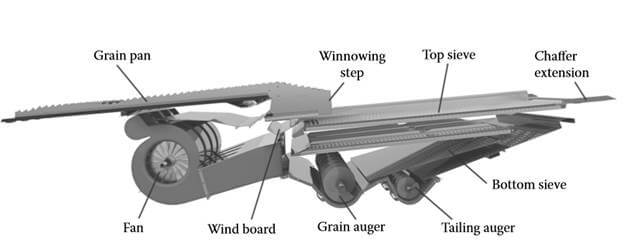
The cleaning unit of a combine harvester is usually composed of a grain pan, two sieves mounted one on top of the other, and a fan that blows air upward through the bottom of the sieves toward the combine rear. With the use of a fan, a winnowing step takes place between the grain pan and the top sieve (also called the chaffer). The stop sieve has openings with adjustable sizes, while the bottom sieve is replaceable for various crops. The air blows the chaff and straw fragments off, as the grains separate through the openings of the top sieves. Afterwards, an inclined wall moves them to the clean grain auger.
After initial grain segregation through the MOG mixture on the top of the grain pan, the grain separation process takes place in the cleaning unit, as a result of the combination of forces generated by the oscillatory motion in opposite phases of the sieves and the gravitational force. The cleaning procedure occurs successfully thanks to the differences in terminal velocities, together with the grain’s shapes and dimensions.
Construction of Cleaning and collecting unit
Cleaning units can be built with different grain pans, equipped with two or three sieves, and with fans of diverse drives and shapes. Also, the cleaning section may entail a fixed mounting position or may be tilted to compensate the combine inclination when driving on hillside fields. The majority of combine harvesters are equipped with a regular or small grain pan. A set of parallel augers carry the main function of delivering grain and the MOG mixture from the axial threshing. With such design (often used on John Deere combines), the grain pan has to be inclined at a higher angle.
In case of having multiple tangential threshing units, a conventional combine harvesters may have two grain pans to collect and deliver separated material from the threshing units and straw walkers, respectively. Such designs encompass a set of three sieves (chaffer – top sieve, middle sieve and bottom sieve). This solution is applied in Topliner-3 combine series manufactured by SAME Deutz-Fahr, and in the axial-flow RTS-1 combine harvester of the same manufacturer.
When harvesting on hillside fields, the separation and cleaning processes carried out by a cleaning unit are very sensitive to the inclined angle of the combine harvesters. This sensitivity comes from the issue that the material slides to the downhill side of the sieves, and the airflow escapes on the upperhill side. The collecting of material on the downhill side of the sieves affects negatively to the material delivery and grain separation, and thus resulting in higher grain losses on farms. Moreover, a higher airflow passing through the upperhill side of the sieves means a larger amount of grains being discharged, while separated grains are accompanied by a greater amount of the MOG mixture. The cleaning unit moves synchronously, unlike the combine frame rotation when the combine harvester works on the inclined surfaces.
Combine Grain Pan
There are two main roles that the grain pan of a cleaning unit is required to execute:
- Transporting the separated grain and MOG mixture from the threshing unit or straw walkers to the chaffer (top sieve).
- Segregating the grain through this mixture on the top surface of the grain pan.
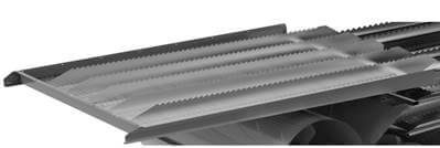
During the segregation process, the grains fall through the pan extension on the chaffer (top sieve) and are accelerated, together with the airflow from the fans which makes it very efficient for the winnowing step. The surface of the grain pan is usually divided by equidistant walls that are perpendicular to its surface. The wall’s role is to mitigate the lateral flow or agglomeration of the MOG and grain mixture, as the airflow distribution in the transversal cross area is not uniform.
Combine Top Sieve (Chaffer Sieve)
The separation of small fragmentation of straw from the MOG-grain mixture is executed by the top sieve (or chaffer). The chaffer can be found in two models: the Graepel sieve, or the adjustable-louver sieve.
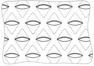
The latter sieve type is more commonly used by combine harvester manufacturers. The adjustable components are mounted on rods whose ends can spin with an angle between 0° and 45° into the sieve frame, and thus diversifying the sieve opening size. The profile of adjustable louvers can be curved, called the Petersen type, or of a spline shape. They are often built from galvanized or stainless steel, or even from plastic. The typical length of the chaffer falls around 1.1-1.5 m (43.3-59 inches).
Combine Bottom Sieve
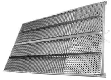
The bottom sieve of the cleaning shoe contains a perforated sheet metal with a round or rectangular shape opening. For some special cases, a sieve with adjustable louvers can be utilized as well. The sieves have an inclined angle of 1°–7°, with the lifted end located at the exit where fragmentation of straw and chaff are blown out onto the farms. The chaffer extension can be applied at an inclination of 7°–30° for the optimized recovery of unthreshed, fragmented ears.
Fan
Function of Fan
The pneumatic forces generated by the airflow from the fan help the grain cleaning procedure occur efficiently. The airflow has the function of moving light items in the MOG mixture and evacuating them out of the combine harvesters. The pneumatic forces are required to be higher than gravitational forces acting on the MOG particles. However, the pneumatic forces must also be lower than the gravitational force acting on grain.
Therefore, a certain range of air speed is needed for simultaneously satisfying both above-mentioned conditions. Moreover, the airflow must be evenly distributed across the width of the sieves and significantly decrease from the front to the rear of the sieves, in order to prevent the throwing out of some grains on the farms.
In the winnowing steps, the ideal air velocity should be 6-8 m/s (19.7-26.25 ft/s). The values should be 5 m/s (16.4 ft/s) at the chaffer’s front side, and no more than 3 m/s (9.8 ft/s) at the end side. The airflow direction should be around 30° to the horizontal. If on sieve, such direction should be ranging between 20°–30°. A fan, or a series of fans mounted on the same shaft generates the required airflow for the winnowing steps, and is powered by a driving transmission of the combine engine.
Fan types
The two most popular fan types installed in a combine harvester cleaning unit are the cross-flow fan, and the centrifugal radial-flow fan. The fan types are featured by the airflow path through the fan.
Centrifugal radial-flow fans
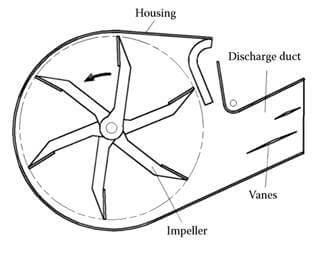
For low to medium airflow rates at high pressure conditions, centrifugal fans are ideal selections, as they can handle high-particulate airstreams like in the case of combine harvester’s cleaning units.
With the assistance of a rotating impeller, the radial-flow fan can easily increase its airstream velocity. The impeller is composed of a shaft mounted on two bearings, together with four to six radial blades mounted on radial arms. It rotates into a cylindrical sheet metal housing whose longitudinal axis does not coincide with the rotation axis of the impeller. The air intake circular openings are located on the housing. However, most of the airflow is streamed through the lateral sides.
In some versions of radial-flow fans, the airflow can be regulated via the use of a sliding throttle plate that adjusts the effective width of the impeller exposed to the airstream. The airstream then radially travels through the blades to the air discharge divergent duct, where the airflow direction is controlled by one or two stabilizers (or vanes).
Cross-flow fans
The cross-flow fans are capable of generating high pressures at low rotating speeds, and even in tough operating conditions. The fan’s housing consists of a front guide and a rear guide divided by an open air intake space that extends over the whole length of the fan. Following the housing is the fan’s air discharge duct, as well as one or two stabilizers with adjustable airflow direction.
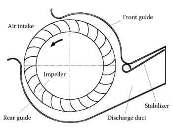
When the impeller of cross-flow fans rotates, the air is sucked through the air intake opening of the housing, and transversally passes the inner area of the impeller before being discharged through the duct. A cross-flow fan produces a relatively high pressure at low rotating speed thanks to the air passing through the impeller blade not once, but twice. Low rotating speed provides two advantages: (1) it provides a lower level of noise, and (2) it does not require high-strength attributes of blade fans.
Auger Elevator
In the building of agricultural harvesting machinery, the auger elevator (or screw elevator) is used for conveying grains, unthreshed ears, chopped vegetal material and chaff. The utilization of auger elevator provides certain superiorities, such as compact design, low maintenance, and the continuous conveying flow of materials. However, the auger elevator entails some drawbacks as well, including their restricted length and inability to convey lumpy materials.
The core function of an auger elevator is to move the particulate from one elevation to a higher one, at a certain inclination. The auger elevator comprises a circular barrel (tube) rigidly mounted on a driving shaft. The auger is made of sheet metal.
The conveying efficiency of an auger conveyor is determined as the ratio between the actual feedrate and the theoretical feedrate resulting when the auger channel is full and the particulates are elevated with the axial speed (with no slip or rotation). The efficiency is lowered as the clearance between the barrel and screw auger increases.
Grain tank
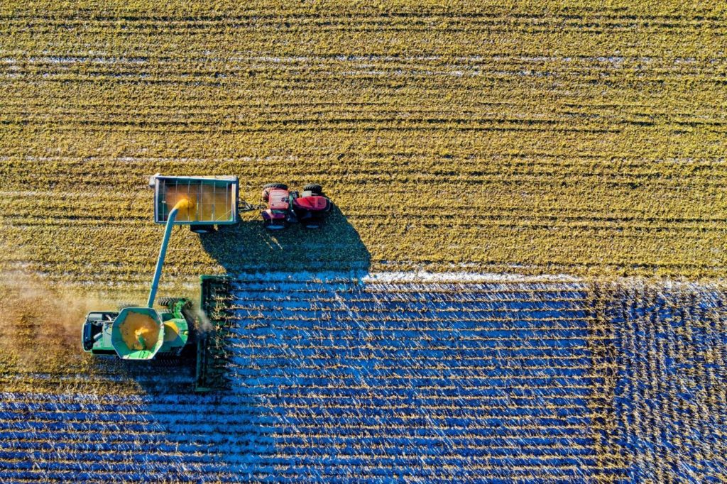
After the grain falls through combine sieves, and its chaff is carried by the straw walkers towards the back of the harvesters, the final amount of grain is elevated and stored in a collecting tank. As the grain tank fills, it shall be emptied into a trailer via a side pipe called an unloader. Regarding the chaff, it is either spread out on the farms or baled up for later use.
The grain is collected in a tank located in the combine harvester. This grain tank is periodically emptied into carts run by tractors that move alongside. The chaff and the stalks are discharged from a big exit pipe at the back of the combine harvester and fall onto the soil surface.
The grain (or the seeds at the top of each plant) has many applications in real life, such as making bread and cereal. However, the chaff (dry coatings of the seeds) are inedible and have to be discharged, together with their stalks. Some stalks are usable for animals feeding, though.
Conclusion
Reaching the final stage of the work chain – the cleaning unit, the threshed grains fall through the sieves and are delivered to the grain tank for storage. Besides grain tank, the cleaning and collecting unit of combine harvesters is mainly composed of a grain pan, two sieves (top sieve – chaffer, and bottom sieve), a fan and an auger elevator. Each compartment has its own function. The grain pan operates with its oscillatory movement to shake the MOG mixture, which contains mainly straw and chaff.
Then, two sieves are used for filtering the grains for storage. Thanks to their heavier structure of grains, they fall onto the sieves under gravitational forces. After falling through the sieve system, they are conveyed to the grain tank via the operation of an auger elevator. Regarding the lighter part – the MOG mixture, they are blown by the airflow generated by the fan and are pushed toward the combine rear for discharging on the field. The cleaning and collecting system completes and finalizes the work of a combine harvester, as the grains are successfully harvested, and the residual MOG mixture are clean and discharged on the field for use in other purposes.
Link out and prosper!
https://books.google.com.vn/books/about/Combine_Harvesters.html?id=yn5jCgAAQBAJ


