
Meta: Exploring seven main elements of the combine harvester power system in this article. You will know thoroughly how this machine can achieve a smooth operation.
As a fundamental factor of general performance, combine harvester power system plays a key role in ensuring the proper operation of the machine.
Basically, the system involves the combination of seven crucial elements, namely engine, transmission system, steering mechanism, wheels, levelling, hydraulic, and electrical and electronic systems.
So, how do these elements coordinate with each other to give the combine harvester a smooth operation?
Let’s discover the combine harvester power system and address all of your questions in this article.
Overview Of Combine Harvester Power System

Modern combine harvesters achieve high capacity for material processing and fast ground speed on the field.
This ground speed varies in accordance with crop variety, crop type, and field conditions.
Those are good reviews on the overall features of combine harvesters before we move on to further explorations.
An up-to-date combine harvester calls for different power systems (mechanical, hydraulic, pneumatic, electric, and electronic) for propulsion, driving, actuating, and control of its processing equipment and systems correspondingly.
Besides, some of the engine power is utilized for combine process control as well as cab environment control such as heating and air conditioning.
In the combine harvester power system, the propulsion system is composed of a diesel engine and a power transmission system.
It will be ideal if the engine operates constantly at a rotation controlled by the engine control unit.
The classical combine harvester power transmission system consists of a master clutch on the input shaft, a manual stepped transmission, a differential, drive axles, final reduction drives, and brakes.
The driving system concludes the master clutch, parking brake, gearshift mechanism, steering system, and engine control unit.
Element #1: Engine

A modern combine harvester is typically equipped with a diesel engine to generate power for all functional systems of the machine, along with propelling it when operating.
A typical engine includes six to eight cylinders and develops a nominal power within the range of 150-300 Kw (200-400 hp).
The load on the engine fluctuates in line with the loads applied by multiple assemblies which are activated, operated, and deactivated during the use of the machine.
Hydrostatic drives consume more power than conventional stepped drives, particularly on slopes with the grain tank fully loaded.
The harvester commonly operates at a set engine speed such as low speed (about 1,200 rpm), medium speed (about 1,600 rpm), and high speed (more than 2,000 rpm) to ensure the proper combine harvester power.
Once the operator has selected the speed, the engine control unit handles the speeds by dynamically modifying the amount of fuel injected into the engine cylinders.
The engine control unit may use a power curve or an algorithm for a power curve to actively regulate the fuel flow rate, thereby modifying the engine power.
It is also possible for an engine control unit to combine input from a proactive algorithm with input from a reactive algorithm.
Element #2: Transmission Mechanism
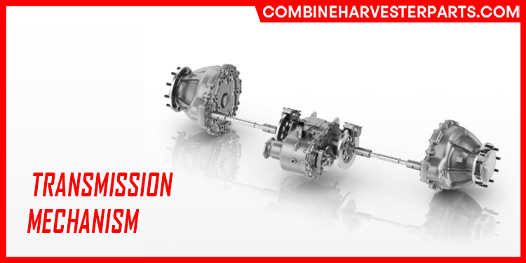
Self-propelled combines were originally featured with conventional stepped transmissions.
The input shaft rotation of this mechanism was adjusted using a continuous variable transmission that was mechanically or hydraulically controlled to enable the operator to speed up or slow down.
A clutch was still required for stopping the machine or altering transmission gears.
This kind of transmission results in an excellent efficiency: above 90% for the gearbox and 85%-87% for the total transmission system.
Nonetheless, this technical solution does not bring about an efficient split of the mechanical power flow needed for crop processing and that demanded for combine propulsion.
The most recent trend in combine propulsion is applying a hydrostatic continuous variable transmission (CVT) that allows a successive alteration of the ground speed of the machine while keeping the constant engine speed needed for steady operation of material processing systems.
After 1995, there was an introduction of hydrostatic continuously variable transmissions with automatic control for standard tractors.
A CTV facilitates an infinite transmission ratio of nominal speed down to zero, while the speed of the engine is constant.
The most basic hydrostatic CTV is a system that includes at least one hydrostatic pump and a motor.
Noticeably, at least one of these units must be equipped with a continuously variable displacement.
Additionally, the engine turns the variable-displacement pump, which can generate high flow rates at very high pressure of transmission fluid.
Then, the pressurized fluid is directed to the variable-displacement motor to get a high efficiency.
The motor displacement is commonly higher than the pump displacement.
A CVT’s driving shaft may have a constant angular velocity over an array of output speeds.
By letting the engine run at its most powerful rotational rpm, this translates into better fuel efficiency than other transmissions.
Element #3: Steering Mechanism
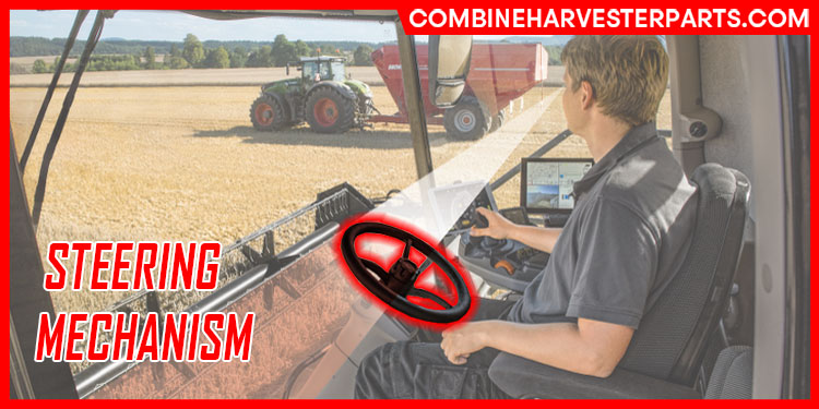
The basic hydrostatic steering mechanism in the combine harvester power system consists of the following components: steering wheel, steering unit, gear pump, tank with oil, and steering cylinder.
In particular, the steering unit is fed with oil by a fixed-displacement pump.
When the steering system is already turned, the steering unit guides an oil flow rate to the matching side of the steering cylinder whilst the oil from the opposite side runs toward the tank.
The flow rate for oil is proportional to the steering wheel’s rotation angle.
If the engine is not steered, the oil is pumped into the steering mechanism at a low pressure.
Besides, some features of the steering mechanism may also have been improved, namely loading sensing, oil flow amplifying, and electrical control.
It is possible to integrate power steering, electrohydraulic power steering, and steering sensors to create an auto-guided steering system.
This auto-guided system can be paired with a global positioning system (GPS) receiver, allowing auto-guidance of combines in the field, tracking of machine position in the field, and gathering of harvest yield data.
Element #4: Wheels
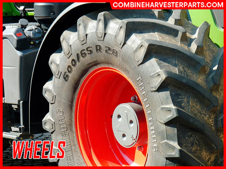
With regard to wheels in the combine harvester power system, combine harvesters are constructed with rubber wheels, which are figured for dry or paddy fields.
Standing apart from the front axle and rear axle, the wheels’ size depends on combine weight and load, and on maximum allowable pressure on the soil as well.
For instance, paddy-use tires can be categorized into high-lug tires, wide-lug tires, and paddy-lug tires.
Test studies show major variations in soil compaction rates from a combine harvester, based on the tire make and the kind of tire installed.
This can have a big effect on the growth of plant root and crop production, including in crop rotation.
When conditions of very wet soil are observed, the pressure of tire inflation will be decreased to the minimum required for the load being carried.
To reduce the soil compaction, the weight is uniformly distributed over a large footprint,
which means it is needed to use wider tires, dual tires, or a self-levelling track system with tandem wheels.
The track provides better grip in wet and muddy conditions, and simultaneously scatter the combine weight,
making it possible to decrease the soil compression, while the driven rear axle easily turns the machine.
If driving the combine on the road at moderate speeds is not extreme,
slightly lower pressure in the tires can be applicable, but only if the change meets the manufacturer specifications.
Element #5: Chassis/Cleaning Leveling
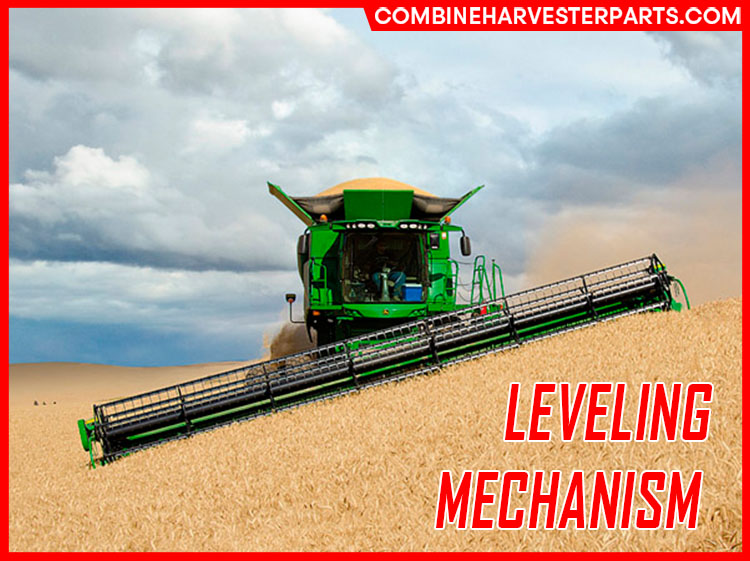
The modern combine header can be sloping up to a certain degree for harvesting the crops on the hillside field.
Nevertheless, if a combine is not equipped with a levelling system, the threshed material tends to move to the lower side of the straw walkers and cleaning shoe.
This leads to losing the air blown by the fan through clear openings of the sieve.
As a result, the straw walkers and cleaning shoes will perform less efficiently and there will be an increase in the grain losses.
In fact, the design of each levelling system all has a distinct limitation in the matter of the slope, quantifying the terrain inclination to the horizontal.
Typically, the slope is represented as a percentage (tangent of the angle of inclination × 100).
The angle tangent is the fraction between the rise (distance calculated on the vertical) and the run (distance calculated on the horizontal).
Though hillside levelling calls for a complicated design,
there are a number of advantages concerning the enhanced processing efficiency on sidehill and normal threshing, separation, and cleaning operations,
ensuring the combine harvester power system’s work.
These features enable the straw walkers to operate at the highest MOG throughput, whilst remaining the grain loss at a low level.
Subsequently, leveling contributes to advancing the stability of the combine on the hill by keeping the gravity center of the machine,
within the area determined by the points of wheel contact with the soil.
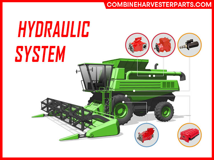
Element #6: Hydraulic System
Regarding modern versions of combine harvesters,
it is essential to meet the requirements of high processing capacity, efficiency, easy operation, and maximized reliability during the harvesting process,
while maintaining the grain quality. To reach this final target, the hydraulic system plays an integral role in the general combine harvester power system.
High-performance hydraulic drives and control systems are important components to produce and regulate the movement (speed, direction of speed, acceleration, and damping), as well as the location of the machine’s various mechanical processing units.
The header’s hydraulic system plays its functions for two modes with the combine: transport mode and operating mode, which is applied for most types of combine harvesters.
When the combine runs down the road, the headers vibrate according to the road irregularities, paired with rubber tire elasticity.
The header vibrations’ hydraulic active damping hinders the machine from becoming uncontrollable, enables a higher driving speed, and improves the driver comfort.
As a part of co combine harvester power system, the hydraulic system helps:
- Lift the header at a certain height over the soil when harvesting tall crops (corn, sunflower). The pitching movement is reduced by active vibration compensation.
- Tilt the header for harvesting crops on hillside fields.
- Lift the header to ensure constant pressure on the ground (e.g., for picking up crop swaths). This also prevents possible damage to the header, cutter bar, and crop separators.
- Lift the reel.
- Horizontally position the reel relative to the cutter bar.
- Rotate the reel.
- Reverse the rotation system for the header auger and feeding conveyor.
If mechanical-shift gearboxes and a hydraulically controlled variable-speed drive are used, the gears can be shifted while the engine is in motion.
Shifting through a frictional connection makes the gear less inclined to failure as a consequence of improper shifting.
The hydraulic systems and electrohydraulic systems are controlled automatically or by the combine operator conforming to harvest conditions.
Element #7: Electrical, Electronic, And Control Functions
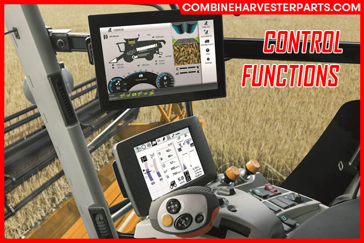
Electrical, electronic, and control systems have various roles, such as:
- Increasing machine/operator productivity
- Maximizing machine availability and adaptability to various crops and harvesting conditions
- Preserving quality of harvested grains
- Minimizing harvesting grain losses and costs
- Reducing operator stress while improving overall machine operability
- Acquiring data about the crop (yield mapping, moisture, maturity)
- Integrating harvest management
Such systems are linked to mechanical components, a hydraulic system, multiple sensors, GPS, an information and control center in the cab, and possibly the harvest management control center.
According to the study of Petre Miu, the electronic and control system may execute control functions of the following systems and working units of the combine:
- Engine power control
- Axle hydrostatic drives with fixed- and variable-displacement motors and auxiliary drives for steering axles
- Single-wheel drives with electronic anti-wheel-slip control
- Electronic drive management with control units
- Implementation of hydraulics with load-sensing systems
- Leveling of hillside combine or cleaning shoe
- Hydraulic steering and remotely powered braking systems
- Automatic steering down the crop row for corn and sunflower harvesters
- Electrohydraulic header/component control (cutter bar position, platform height, vertical and horizontal position of the reel)
- Fan drives
Conclusion
The introduction of combine harvesters has been an indispensable part in the mechanization of agriculture.
Understanding how a combine harvester works enables the farmers and technicians to make the best use of this machine.
In particular, combine harvester power system, as discussed above, plays an essential role in delivering an effective and efficient performance.
The article has presented the combine harvester power elements’ functions and specifications that should be taken into account.
The description of the components of the combine harvester power system helps the information seekers answer the questions related and broaden knowledge as well.
We hope you enjoy it and thank you for reading!
For further articles on combine harvesters, you can pay a visit to our other writings and explore all about this innovative machine.
Frequently Asked Questions On Combine Harvesters Power System
I will dedicate this part to answer all your questions relating to our topic of combine harvesters power system. Let’s start right away.
References
- Aumer, W. (2008). Conceptual comparison of electrical and hydrostatic propulsion in combine harvesters. Landtechnik, 63(2), page 88-89.
- Miu, P. (2015). Combine Harvesters: Theory, Modeling, and Design. CRC Press.

