
If you are so tired of all the hassle of Stick Welding, then you should definitely check out Flux Cored Arc Welding. This process had erased all those hassles and brought superior advantages to the job.
In this article, let’s uncover all the basic information about Flux Cored Arc Welding, from:
- What exactly is Flux Cored Arc Welding?
- Benefits and drawbacks of using Flux Cored Arc Welding.
- Basic equipment of Flux Cored Arc Welding.
- The complete process of Flux Cored Arc Welding.
- Some brief comparisons between Flux Cored Arc Welding and MIG, Stick Welding.
No more waiting! Let’s jump right in!

What Is Flux Cored Arc Welding (FCAW)?
In this first section, we will look over some general definitions and how flux cored arc welding is applied in the real world.
1. General Definition About Flux Cored Arc Welding
Flux Cored Arc Welding, sometimes referred to shortly as FCAW, is a semi-automatic (or automatic) arc welding process that utilizes a continuously-fed consumable tubular electrode (Flux Core Wire) and a constant-voltage power supply (mainly DCEP settings).
Being considered as the sub-type of MIG welding process, FCAW was firstly invented in the early 1950s as an upgraded version to Stick welding (or Shielded Metal Arc Welding, SMAW).
It has many superior advantages over its stick welding pal, one of which is the removal of the bulky external shielding gas. This change helps Flux Cored Arc welding overcome many limits that belong to the SMAW process.
If I have to point out two special traits of Flux Cored Arc Welding, it would be “high welding speed” and “high portability”.
One unique feature of Flux Cored Arc Welding lies in its flux core wires. Upon being melted, the flux composition inside the hollowed core of the wires generates shielding gas and later, slag layer, to protect the weld puddle from contaminants.
2. Two Popular Types Of Flux Cored Arc Welding
Flux Cored Arc Welding has two common process types: self-shielded FCAW (or FCAW-S), and gas-shielded FCAW (or FCAW-G).
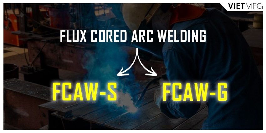
The difference between the two above process types is the composition of fluxing agents located inside the flux core wires.
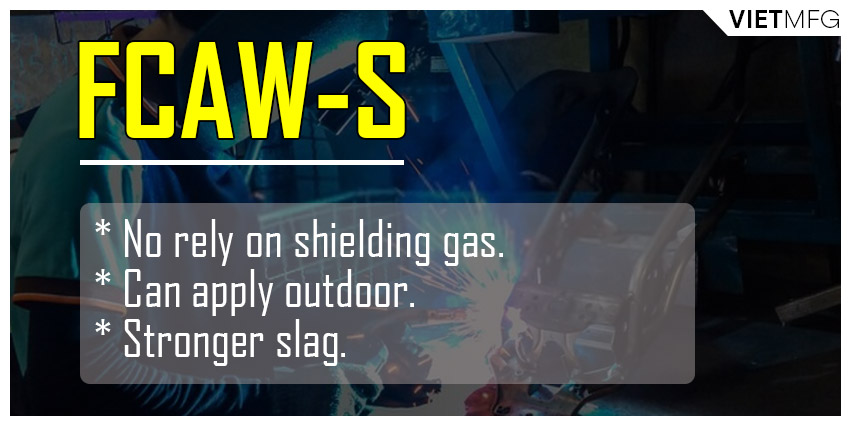
Self-shielded Flux Cored Arc Welding (FCAW-S)
The fluxing agents in self-shielded FCAW bear two functions: to deoxidize the weld pool and to shield the weld pool and metal droplets from contaminants. Thus, it does not rely on the external shielding gas and can be performed in outdoor conditions.
The flux composition in gas-shielded FCAW is quite similar to that in self-shielded FCAW, but its degree of protection in the weld pool is weaker. Hence, the slag created by this type is easier to remove. However, you will need external shielding gas for this particular FCAW type.
FCAW-S is often applied outdoors or for projects with special requirements (such as welding galvanized steels). You will find FCAW-S in many outdoor constructions where the bulky cylinder of shielding gas is not readily available.
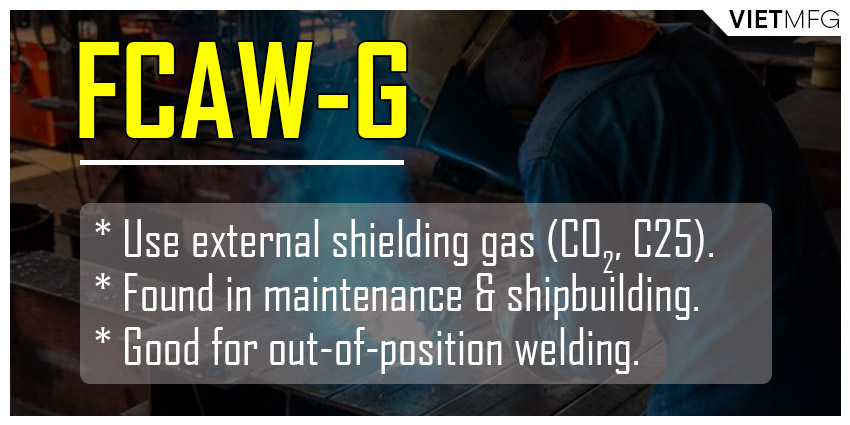
Gas-shielded Flux Cored Arc Welding (FCAW-G)
FCAW-G was created mainly to weld structural steels. It is sometimes referred to as the combination of MIG welding and Flux Cored Arc Welding.
The most commonly shielding gas applied for FCAW-G is either Pure CO2 or the C25 (75% Argon and 25% CO2).
FCAW-G is commonly found in maintenance and shipbuilding projects. Out-of-position welding, such as vertical up or overhead, becomes easier with FCAW-G.
3. Which Metals Can Flux Cored Arc Welding Be Applied?
Flux Cored Arc Welding can be performed on most mild steels, stainless steels, cast iron and other surfacing alloys. Among them, flux cored welding stainless steel is commonly used.
However, flux cored welding aluminum is not possible. There is a reason behind it, and we will discuss it separately in another article.
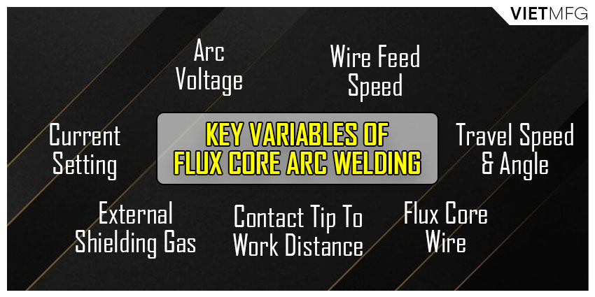
4. Key Variables Of Flux Cored Arc Welding
Flux Cored Arc Welding is characterized by the following features:
- Arc voltage (utilizing constant voltage power supply).
- Wire feed speed.
- Travel speed and travel angle.
- Flux core wire type, extension and angle.
- External shielding gas (in FCAW-G).
- Current setting (DCEP for FCAW-G and DCEN for FCAW-S).
- Contact tip to work distance (CTWD).
Advantages And Disadvantages Of Flux Cored Arc Welding
This following part is all about why Flux Cored Arc Welding is so preferred, as well as some limits of this welding process.
1. Advantages Of Flux Cored Arc Welding
Here are some reasons why we must use Flux Cored Arc Welding:
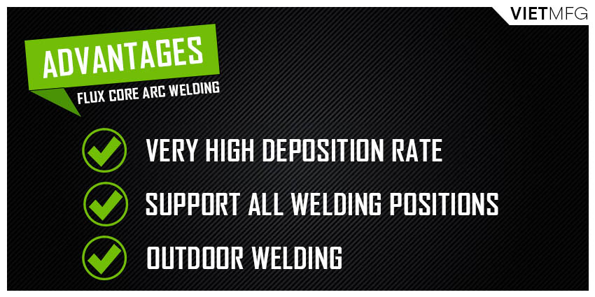
- It offers high-quality weld results with excellent appearance.
- It has unmatched electrode deposition rates, which is why this process is very productive (for FCAW, the deposition rate can go up to 25 pounds per hour, while that of MIG is only 8 pounds per hour).
- It can be welded in all positions, as long as you use the right flux core wires.
- It is applicable in outdoor conditions, thanks to the independence of external shielding gas.
- It features deep weld penetration (more than stick welding).
- It requires less pre-cleaning effort than the MIG process.
- There is very low chance of porosity.
- It can be applied with various metal types with a wide range of thickness.
- It demands less skill from the operators than in other welding processes. All you need to do is learn to set up the machine properly, and hold the welding torch over the correct spot.
2. Disadvantages Of Flux Cored Arc Welding
Every coin has two sides. And Flux Cored Arc Welding is no exception. Let’s go over some drawbacks of this welding process:
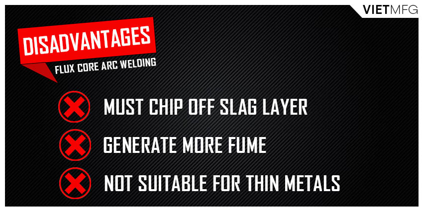
- You must chip off the slag layer after welding, or after every single pass (if it is a multi-pass procedure).
- Flux core wires are more expensive than solid MIG wires or any other welding wires in general.
- It requires more complex equipment than Stick Welding.
- It generates more fume than in other welding processes, especially in MIG welding.
- It cannot be performed on non-ferrous metals, such as aluminum.
- It is not recommended for use on thin metals (thinner than 20 gauge).

Basic Equipment Of Flux Cored Arc Welding
There are 7 basic equipment required for Flux Cored Arc Welding:
- A constant-voltage power supply.
- A wire feed system.
- A welding gun (or torch).
- Welding cables.
- External shielding gas, if required (FCAW-G).
- Fume extractors, if needed.
- Seam followers and motion devices, in case for automatic welding machines.
However, we will discuss some core items that are must-have equipment for Flux Cored Arc Welding.
1. Constant-voltage Power Supply
Normally, the power source for flux cored welders operate on 120 or 240 volts of input current.
It may function on either the single phase or three-phase input with a frequency of around 60 hertz.
Most power supply sources for flux cored welders have a duty cycle of around 60 percent, which means they can run continuously for 6 out of 10 minutes.
The Flux Cored Arc Welding process can use either DCEP or DCEN current settings. Normally, gas-shielded FCAW runs great with DCEP, while self-shielded FCAW can be operated on either of the two settings.
DCEP offers deeper weld penetration, which is great for dealing with thick metals. However, DCEN is superior in welding thinner metals with poor fit-up conditions.
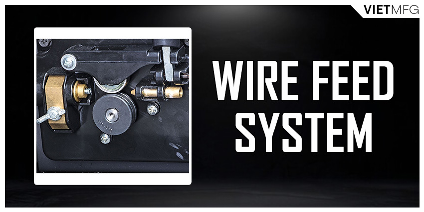
2. Wire Feed System
A wire feed system offers energy to drive the flux core wires through the cable and the welding torch to the metal workpiece.
It usually has an electrical rotor linked to a gearbox that locates the drive rolls.
There are some different systems available, depending on your application.
However, most of them are constant-speed type, which means they go with a constant-voltage power source.
For variable-speed type, a voltage sensing circuit must be installed to maintain the optimal arc length, as fluctuation in the wire feed speed can change the arc length.
3. Welding Guns (or Torches)
Flux Cored Arc Welding utilizes both air-cooled and water-cooled guns.
Water-cooled flux core guns offer more effective cooling to the gun itself. They are highly recommended for welding current over 500 amperes.
Air-cooled guns are found mostly in welding projects with current below 500 amperes. They are more lightweight and easier to manipulate.
4. Equipment For External Shielding Gas
To apply shielding gas externally in FCAW-G, we will need a gas supply hose, a gas regulator, some control valves and a supply hose to the welding gun.
The shielding gas itself can be contained in gas form in high pressure cylinders, or in liquid form when stored in tanks with vaporizers.
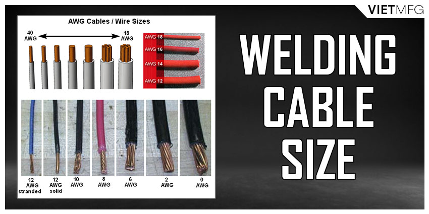
5. Welding Cables
Welding cables are used to connect the power source to both the metal workpiece and the welding gun.
They are normally made of copper for better electricity delivery.
The cables contain hundreds of copper wires that are enclosed in an insulated casing of synthetic rubber.
The welding cables that link the power source to the welding gun is referred to as the “electrode lead”.
Their sizes depend on the output capacity of the flux cored welders, as well as the machines’ duty cycle and the distance between the welding machines and the workpiece. The sizes measured according to American Wire Gauge (AWG) of these cables range from AWG No 8 (0.1285 mm) up to AWG No 4/0 (0.46 mm).

The following table will provide you with the recommended cable sizes for application with different welding currents and cable lengths:
| Weld Type | Weld Current | Cable Length (in feet) – Cable Size (as per AWG) | |||||
| 60 ft | 100 ft | 150 ft | 200 ft | 300 ft | 400 ft | ||
| Low duty cycle (Manual) | 100 | 4 | 4 | 4 | 2 | 1 | 1/0 |
| 150 | 2 | 2 | 2 | 1 | 2/0 | 3/0 | |
| 200 | 2 | 2 | 1 | 1/0 | 3/0 | 4/0 | |
| 250 | 2 | 2 | 1/0 | 2/0 | |||
| 300 | 1 | 1 | 2/0 | 3/0 | |||
| 350 | 1/0 | 1/0 | 3/0 | ||||
| 400 | 1/0 | 1/0 | 3/0 | ||||
| 450 | 2/0 | 2/0 | 4/0 | ||||
| 500 | 2/0 | 2/0 | 4/0 | ||||
| High duty cycle (Automatic) | 400 | 4/0 | 4/0 | ||||
| 800 | 4/0 | 4/0 | |||||
| 1200 | 4/0 | 4/0 |
6. Flux Core Wires
This is a huge topic to discuss in just a few lines of words.
I had prepared a separate article just for this flux core wires topic. You can check it out for more in-depth analysis.
The Complete Process Of Flux Cored Arc Welding
Here, I will show you the complete process of how to perform Flux Cored Arc Welding.
1. Safety First!
Before laying down any weld bead, you must ensure to have decent safety apparel on to remove any potential fire hazards in your workplace.
Key safety apparel consists of leather shoes (or boots) and leather gloves, cuffless full-length pants, a long-sleeve and fire-resistant jacket, a welding helmet, safety glasses and a bandana to protect the top of your head from spatter.
Safety gadgets must always be your first priority when performing Flux Cored Arc Welding (and other welding processes as well).
2. Preparing Your Metal Workpiece
As mentioned in the advantage section, Flux Cored Arc Welding requires less pre-clean efforts from operators. FCAW has higher tolerance of surface contamination than other welding processes.
However, it does not mean you can just pick up the metal pieces that are full of dirt and start welding right away.
Before performing Flux Cored Arc Welding, you should clean your metal workpiece with a metal brush or a grinder.
Moreover, make sure to clean the area of your base metal where the ground clamp will be attached. Rusty surface can weaken your contact, create higher resistance in the welding circuit and result in poorer weld quality.
For metal thickness over 1/4 inch, it is a good idea to bevel the edges of your workpiece to ensure complete fusion of the two metals. This is very effective for butt joints.
3. Gathering Essential Equipment
First thing first! Check your welding cables. Make sure all of them are tightly secured and free from any potential damage.
After that, pick up an electrode polarity. The polarity settings (DCEP or DCEN) are usually found on the internal section of the flux cored welders, near the drive rolls.
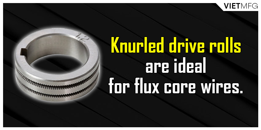
Speaking of drive rolls, remember to use the correct type. Normally, for flux core wires, knurled drive rolls are ideal as it provides a good “bite” on the wire without deforming it.
Then, check your wire tension. Too little or too much tension on the drive rolls can result in poor wire feeding performance.
Also, inspect your consumables (contact tips, liners, etc). Make sure they are free from spatter and being rusty.
4. Choosing A Suitable Flux Core Wire
This is also covered detailedly in another separate article. Make sure to check it out.
5. Setting Up Voltage And Amperage
Which value to set all depends on the material thickness, joint condition and welding position.
The welder manufacturers often provide those information in the form of reference charts in your purchase to help you set the correct voltage and wire feed speed for your material thickness.
Another alternative reference is the flux cored calculator provided by Miller. You can check it out here.
6. Adjusting The Electrode Stickout
Normally, Flux Cored Arc Welding requires a stickout of about 3/4 inch, which is twice the recommended value for MIG welding.
7. Choosing The Welding Technique: To Push Or To Pull
With Flux Cored Arc Welding, it is always advised to use the drag (or pull) technique. This means the tip of the welding torch is being pointed back at the weld puddle and dragged away from the completed weld.
For quick memory, just remember that: “If there is slag, you drag”.

8. Managing Your Travel Angle
Travel angle is defined as the angle between the welding gun and an invisible line that is perpendicular to the weld joint surface.
In most cases, you should maintain a travel angle of about 5 to 15 degrees for Flux Cored Arc Welding.
Any travel angle beyond 20 degrees can lead to more spatter, unstable arc and less weld penetration.
9. Adjusting Your Work Angle
Work angle refers to the angle between the welding gun and the welding joint surface.
This figure varies with each welding position.
| Welding Positions | Recommended Work Angle |
| Flat position – Butt weld (180-degree joint) | 90-degree work angle |
| Flat position – T joint (90-degree joint) | 45-degree work angle |
| Flat position – Fillet weld | 60 to 70-degree work angle |
| Horizontal position | Decrease around 15 degrees from Flat positions |
10. Tacking Your Workpiece
After setting up your flux cored welders and preparing yourself technically for the welding process, it’s time to tack-weld each corner of your base metals together.
Make sure you are actually fusing both sides of the workpiece together.
Be consistent!
Welding one side more than the other will result in a lack of fusion.
Once you have done tack-welding your workpiece, you will be able to see the shape and realize that each side is aligned and welded into the correct position.
If not, you need to fix it right away, as any corrective actions after welding is much more difficult.
11. Filling The Remaining Areas With Bead Welds
Now, after tack-welding, you have to go back and fill in the remaining areas with bead welds.
This is where all your preparation on drag technique, work angle, travel angle, electrode stickout comes into effect.
They will all affect the final results of your welds.
Besides all those little details, make sure to maintain consistency throughout the welding process. Do not change any angles or stickout mig-weld.
12. Cleaning Up Your Workpiece
After finishing welding, there will be tons of spatter and slag left from the flux.
It is high time to use a chipping hammer and a wire brush to get rid of all this before you start grinding.
While grinding, make sure that you keep the workpiece safely rested on the guard. Use a pair of pliers and clamp it to one of the outside edges.
If you reach this stage, you are basically done with the flux cored arc welding process.
Flux Cored Arc Welding Tips And Tricks
Despite being a very viable welding process over the years, Flux Cored Arc Welding also presents many challenges. Thus, let us discuss some tips and tricks you could use to enhance your performance with this particular welding process.
1. Avoiding Wire Feed Issues
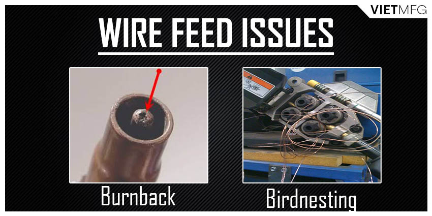
Common wire feed issues include burnback and birdnesting of flux core wires. Such problems can cause massive amounts of downtime.
Burnback
Burnback happens when the flux core wires melt into a ball at the contact tip’s end.
This incident occurs when there is too slow wire feed speed being employed, or when the welding gun is too close to the workpiece.
To prevent this wire feed problem, make sure to use the correct wire feed speed and maintain the proper distance of your contact tip from the workpiece (but no further than 1.25 inch).
Birdnesting
Birdnesting is the problem when the wire is tangled and cannot be fed anymore during the Flux Cored Arc Welding process.
This happens when you do not use knurled drive rolls. Make sure to use knurled V- or U-groove drive rolls in your feeding system.
Moreover, improper drive roll tension can also lead to birdnesting. To set the correct figure, start by releasing the tension on the drive rolls. Then, gradually increase the tension while feeding the wire into the palm of your gloves until one half turn past wire slippage.
Other causes for this issue include the use of wrong liner type, or incorrect trimmed liners.
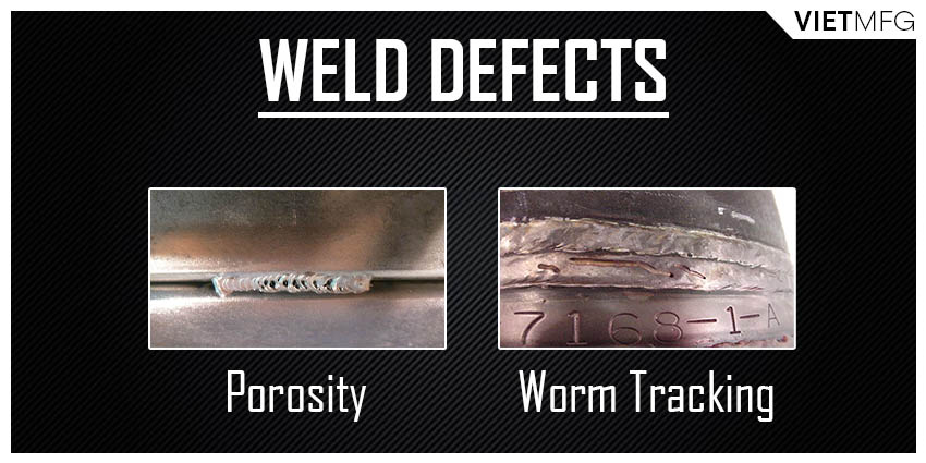
2. Stopping Porosity and Worm Tracking
Porosity and worm tracking are two common weld defects that can lower your weld’s strength.
Porosity
To prevent porosity, make sure to remove rust, paint, coatings, oil, moisture and dirt from the workpiece prior to the welding process.
Maintaining an appropriate stickout is also effective in fighting off this defect.
Worm tracking
To put a stop to worm tracking, which are marks existing on the weld bead surface caused by the flux in the flux core wires, try to avoid excessive voltage.
Follow the recommended data from the filler metal manufacturers for the particular diameter of the welding wire.
Just reduce your voltage slowly by 0.5 volt at a time, until you see worm tracking no more.
3. Getting Rid Of Slag Inclusions
The name says it all. Slag inclusion happens when the slag is trapped inside the weld.
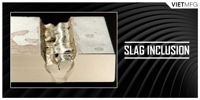
This problem arises from four main reasons: incorrect weld bead placement, wrong travel angle and travel speed, improper weld heat input, and no cleaning action between every pass.
Incorrect weld bead placement
When making multi-pass welding projects, especially on thick parts of the metal, try to place your weld bead in proper positions.
Wrong travel angle and travel speed
In flat, horizontal and overhead positions, your pull angle should range from 15 to 45 degrees. For vertical up position, the drag angle should not exceed 15 degrees.
Whenever you have slag inclusion, let’s try to increase your pull angle and maintain a steady travel speed.
Improper weld heat input
Too low of heat input can give rise to slag inclusions.
Thus, always follow the manufacturers’ suggested parameters for a specific wire size.
If slag inclusions still happen, increase the voltage until the issue disappears.
No cleaning action between each pass
Make sure to remove the slag layer with a chipping hammer, a wire brush or grinding between weld passes.
4. Preventing Undercutting And Lack Of Fusion
Similar to other welding defects, undercutting and lack of fusion increase your downtime. Hence, we need to have solutions to deal with them
Undercutting
Undercutting will weaken your weld metal, especially at the toe area, and often result in cracking.
To deal with this problem, setting up proper welding voltage and current is necessary.
Also, maintain a fast travel speed and employ a weaving technique by pausing on each side of the weld bead.
Lack of fusion
The best advice for this issue is to maintain the correct work angle and heat input.
Changing the work angle and widening the groove to access the bottom part during your welding process when required.
If you are using the weaving technique, make sure to hold the arc on the groove sidewalls.
Moreover, if you find that the flux core wire is getting ahead of the weld puddle, increase your travel speed or utilizing a higher welding current can prevent the problem.
5. Avoiding Excessive Penetration Or Lack Of Penetration
During your welding process, you must be able to control heat input, as too much or too low heat input can cause excessive or lack of penetration respectively.
Excessive penetration
This issue arises when the weld metal melts through the workpiece and hangs below the weld.
It occurs when there is too much heat.
The solution is to lower your voltage, reduce your wire feed speed or increase your travel speed to avoid too much heat at a single spot for too long.
Lack of penetration
This is completely opposite to excessive penetration.
Thus, the solution is also contradictory. Let’s choose a higher wire feed speed, a higher voltage or reducing your travel speed.
A Brief Comparison Between FCAW And GMAW, SMAW
In my opinion, Flux Cored Arc Welding (FCAW) gathers all the great traits of Stick Welding (SMAW) and MIG Welding (GMAW).
Let’s have a little comparison among the three categories.
1. FCAW vs GMAW
Flux Cored Arc Welding is very much like GMAW (or MIG).
Both welding processes are applied for ferrous metals.
They both use welders with continuously wire drive systems.
Their applicable welding wires also offer very high deposition rates.
When performing at high current settings, the two processes produce very smooth arcs.
All in all, Flux Cored Arc Welding can be considered as a subset of MIG Welding. However, there is one difference. And it lies in the type of welding wires employed in each process.
2. FCAW vs SMAW
Flux Cored Arc Welding is more complicated to set up and requires more cost than Stick Welding, as it needs a wire feeder and a welding gun.
The FCAW process also produces more fumes, due to the high currents, voltages and the flux applied.
All of them make FCAW less visible during welding and less portable than Stick Welding.
Troubleshooting Of Flux Cored Arc Welding
Let’s examine some effects when we change each key parameter of Flux Cored Arc Welding.
Wire feed speed
Too low wire feed speed for Flux Cored Arc Welding will make the slag layer more difficult to be removed. It also generates more spatter. The final result is a convex wide weld.
Too high wire feed speed will cause the wire to become stubbing. The final weld will have a shape of a narrow convex bead.
Contact Tip To Work Distance (CTWD)
Too short distance will generate inadequate slag coverage, due to the improper preheating of the flux composition inside the wire.
Too far distance will also make the wire become stubbing, and create inconsistency in the feeding process.
Conclusion
Congratulations on making it here. You have gone over all the basic things about Flux Cored Arc Welding.
Many more in-depth topics await you ahead.
So keep on following my page for more amazing welding information.
Reference
- Flux-cored arc welding. Wikipedia. Retrieved December 26th, 2021.
- Flux Core Welding (FCAW). Weld Guru. Retrieved December 27th, 2021.
- What is Flux Cored Welding?. Praxair USA. Retrieved December 27th, 2021.
- What is Flux-Cored Arc Welding (FCAW)?. TWI Global. Retrieved December 27th, 2021.
- Flux-cored Welding: The Basics for Mild Steel. Miller Welds. Retrieved December 27th, 2021.
- Tips for avoiding common flux-cored problems & improving your FCAW welds. Bernard Welds. Retrieved December 27th, 2021.
- Basic Guide to Flux Cored Arc Welding. Instructables. Retrieved December 27th, 2021.
- The Complete Guide to Flux-Cored Arc Welding. Welding Headquarters. Retrieved December 27th, 2021.

