MIG Welding Wire Selection is the one of the two core contents of MIG Welding. (the other content is setting correct parameters for your MIG Welders).
Thus, this article of our site is dedicated all about this wire selection, with updated and unique information of the content, including:
- Learn how to read the wire’s name.
- Certain criteria you MUST consider before selecting a MIG wire.
- Some in-depth properties of MIG wires.
Alright, let’s dive right in!

Understanding MIG Wire name
Names of MIG wires are simple to read, as it comprises of 4 little parts:
- The first part in a MIG Wire name is always the letter E. This means “electrode”, which is capable of carrying electricity.
- The second part in a MIG Wire name is always the letter R. This indicates “rod”. When you see this in a wire name, it means that the filler rod does not need to be an electrode. For example, in TIG welding, we have a tungsten electrode, and another separate filler rod.
- The third part in a MIG Wire name reveals certain properties or identification of the wire.
- The last part in a MIG Wire name is an optional section, which shows additional chemical composition of the wire.
From only the name, you can extract many useful information which helps you select a proper MIG wire for your welding projects.
Let’s look at several examples, so that you can have a better feel of how to read the MIG wire name.
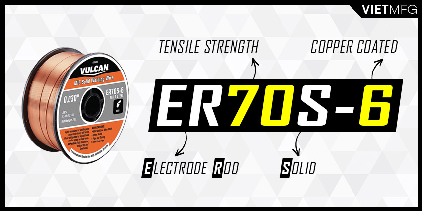
ER70S-6
ER70S-6 is considered one of the most popular MIG wires in the market.
From left to right, the name means:
- E = Electrode.
- R = Rod.
- 70 = A minimum of 70,000 psi tensile strength of the weld metal.
- S = Solid, which means the filler metal is solid.
- 6 = The amount of deoxidizing agent and cleansing agent on the electrode wire. In this particular case, it means a copper coating on the electrode.
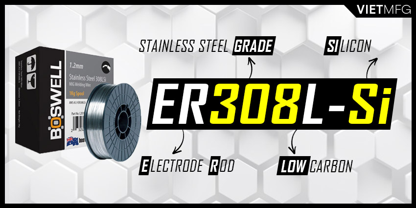
ER308L-Si
From left to right, the name means:
- E = Electrode.
- R = Rod.
- 308 = One particular grade of Stainless Steel that makes up the electrode.
- L = Low Carbon. This indicates the carbon amount in the stainless steel.
- Si = Silicon. This optional part shows that a high silicon amount is added to the MIG wire to help the weld wash into the base metal better.
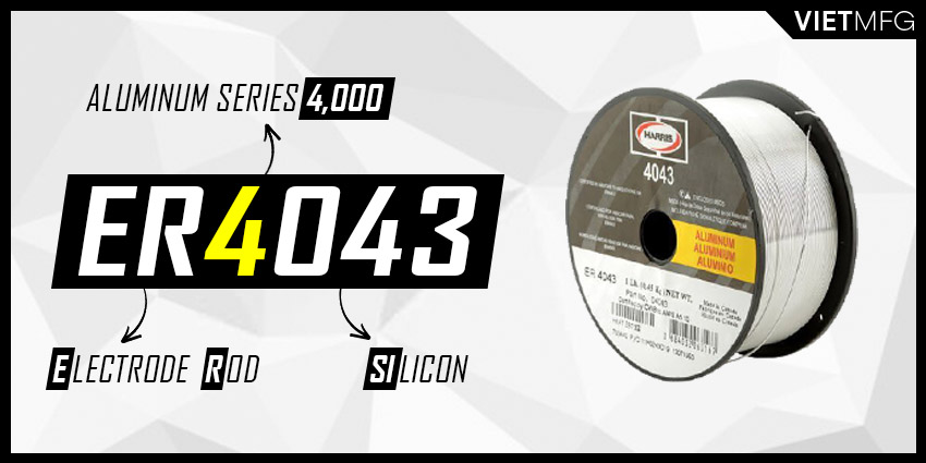
ER4043
ER4043 is also a top candidate for MIG Welding, especially with aluminum grade 2014, 3003, 3004, 4043, 5052, 6062, and 6063.
From left to right, the name means:
- E = Electrode.
- R = Rod.
- 4 = The aluminum series 4,000 that makes up the electrode wire.
- 043 = Indicates the amount of silicon added to the electrode. This silicon amount is the unique composition of 4,000 series of aluminum.
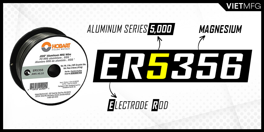
ER5356
ER5356 is a popular choice of MIG wire for welding aluminum grade 5050, 5052, 5056, 5083, 5086, 5155, 5356, 5456.
From left to right, the name means:
- E = Electrode.
- R = Rod.
- 5 = The aluminum series 5,000 that makes up the electrode wire.
- 356 = Indicates the amount of magnesium added to the electrode. This magnesium amount is the unique composition of 5,000 series of aluminum.
Certain criteria you MUST consider before selecting a MIG wire
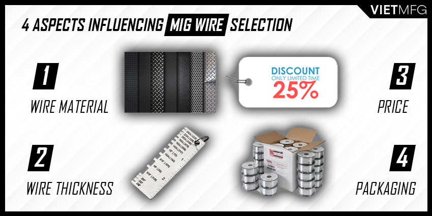
When it comes to choosing a proper MIG wire for your welding projects, there are many aspects that require your careful consideration. Some of those aspects include: the wire material, the wire thickness, the price and its packaging option.
1. Wire’s Material Type
One general rule is to choose the MIG wire with the same material type as your workpiece.
For example, if you are MIG welding stainless steel, then pick a MIG wire made up of stainless steel.
Based on material type, there are 03 main groups of MIG wires:
- Mild Steel MIG Wire.
- Aluminum MIG Wire.
- Stainless Steel MIG Wire.
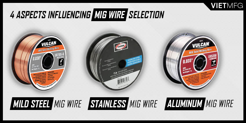
Within each group, the wire can have many variations, due to their different chemical composition.
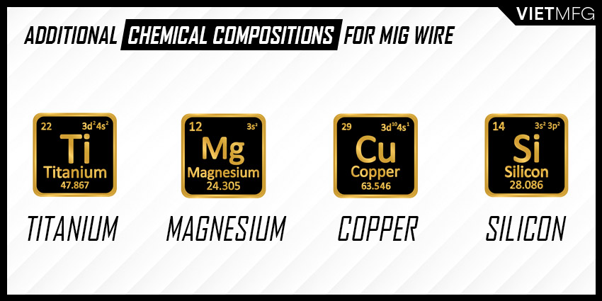
Some wires can have silicon, titanium, copper or magnesium added alongside their core element.
These additions provide great strength and stability to the arc by deoxidizing the weld.
However, the main consideration should always be the core metal.
Consult your manufacturers or follow the instruction that is provided on your MIG welding machines.
2. MIG Wire Sizes (Thicknesses)
The MIG wire’s thickness usually ranges from 0.023 inch to 0.045 inch.
Top 4 most common thicknesses are: 0.023 inch; 0.030 inch; 0.035 inch; and 0.045 inch.
Wires of these thicknesses can be used for most material types, so they are often called “all-rounder” choices.
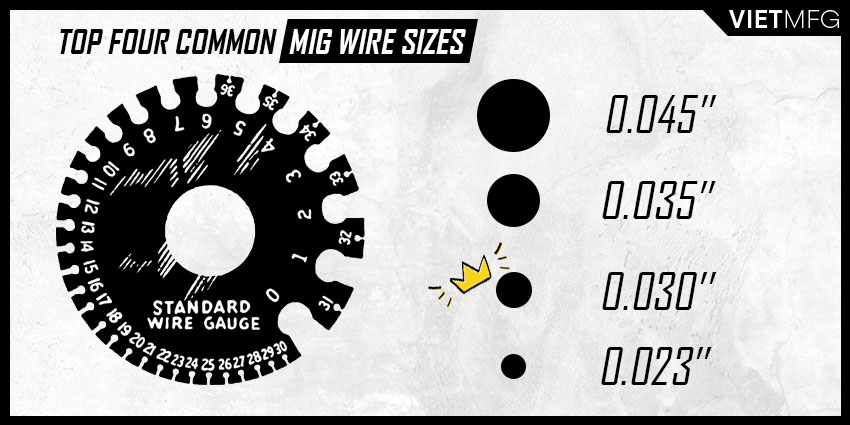
Among those thicknesses, a 0.030 inch wire is the most popular and perfect “all-rounder” choice.
Different electrode sizes shall demand different amounts of power from MIG welders, as well as have different applications.
- Thicker wires (0.035 inch and 0.045 inch) are dedicated for MIG welding of thicker metals at high temperatures
- Whereas on thinner metal sheets, a 0.023 inch wire suits best, as it provides greater control over heat input and significantly reduces burn-through incident.
3. Cost of buying MIG wire
It is estimated that the cost of MIG wire accounts for only 15% of the total cost of welding operation.
However, such a small proportion does not rule out the importance of a correct MIG Wire Selection, as a wrong choice of cheap filler wires would lower the finished weld quality and eventually cost us more.

Moreover, as MIG wires are often ordered in bulk, it is best to evaluate carefully the optimal type for your projects before confirming the order.
This will save you a tremendous amount of money, and also ensure your MIG weld quality.
4. Packaging option of MIG wire
One more aspect that you need to consider when selecting a MIG wire is the packaging option.
Pick a packaging option that allows you to use for about 5 – 6 weeks.
If you left the MIG wires unused for too long, they would not only take up your working space, but also become rust after some time.
Also, remember to keep the MIG wires in dry and warm atmospheric conditions to avoid oxidation.
MIG Wire Selection Recommendation
1. Wire Selection for MIG Welding Stainless Steel
| Stainless Steel Grade | MIG Wire | MIG Shielding Gas |
| 301, 302, 304, 305, 308 | ER308L and ER308LSi | C2 (2% Carbon Dioxide and 98% Argon) |
| 309 Stainless, welding Carbon Steel to Stainless Steel or Low Alloy Steels | ER309L | C2 (2% Carbon Dioxide and 98% Argon) |
| 304,305, 308, 310, 312, 314, 316, 317, 321, 347 and 348 | ER316L and ER316LSi | C2 (2% Carbon Dioxide and 98% Argon) |
2. Wire Selection for MIG Welding Aluminum
| Aluminum Grade | MIG Wire | MIG Shielding Gas |
| 2014, 3003, 3004, 4043, 5052, 6061, 6062 and 6063 | ER4043 | 100% Argon |
| 5050, 5052, 5056, 5083, 5086, 5154, 5356, 5454, 5456 | ER5356 | 100% Argon |
3. Wire Selection for MIG Welding Mild Steel
MIG Wire: ER70S-3, ER70S-6MIG Shielding Gas: C25 (25% Carbon Dioxide and 75% Argon; or 100% Carbon Dioxide.
More advanced properties of MIG Wire you should know
This section will provide information about 4 advanced properties of MIG Wire that you should know. They are:
- Current Density.
- Deposition Rate.
- Electrode Efficiency.
1. Current Density
Current Density shows the amount of current applied to a particular wire diameter.
To understand Current Density easily, let’s do a simple imagination exercise together:
- Let’s think of a PVC pipe. Big or small pipe, it is up to you.
- Now, if we pump water into the pipe, how much water do you think you can deliver through the pipe?
- That’s correct, the answer is it depends on 2 factors: the water pump rate, and the pipe diameter (or your imagination in the first place).
- Then, if you take the water pump rate and divide it by the pipe diameter, you will obtain a value called “water density” applied to that particular pipe.
- The higher this “water density” is, the more water you can deliver through this pipe at one point.
In that exercise:
- The pipe represents the MIG electrode wire.
- The pipe diameter represents the electrode wire diameter.
- The water represents the electrical current.
- The water pump rate represents the current setting applied to the wire.
Current Density is just the same concept as the “water density” above.
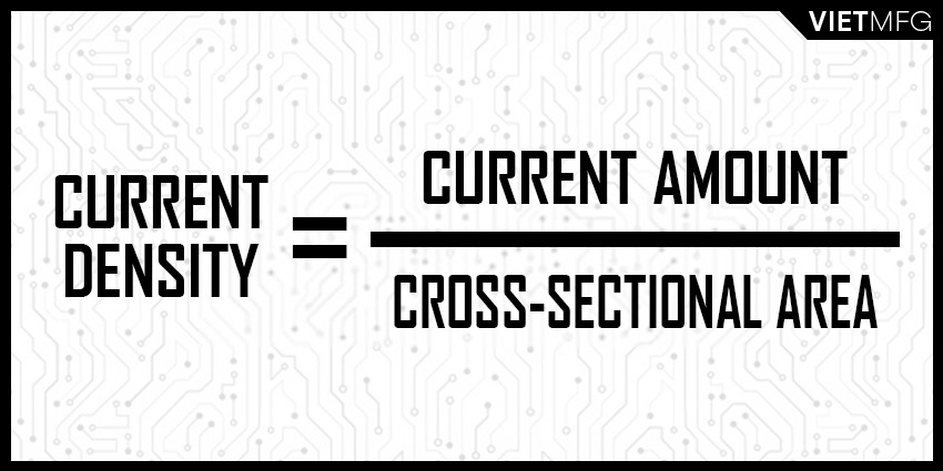
Current Density is calculated as follows: take the current amount applied for a particular electrode diameter (the amount of water), and divide it by the current carrying cross-sectional area (the pipe diameter).
You may find the term “cross-sectional” a little bit tricky. Let us explain for you;
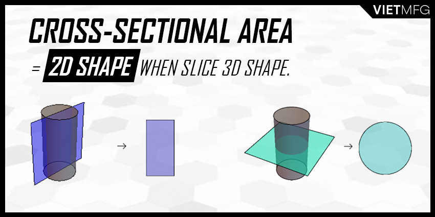
- Cross-sectional area indicates the area of a 2D (two-dimensional) shape that is obtained when you slice a 3D (three-dimensional) object perpendicular to a specified axis.
- Take a 3D object like a cylinder as an example. If you slice it perpendicular to its base, you will obtain a rectangle (2D object).
- However, with that same 3D object (cylinder), if you slice the cylinder parallel to its base, you will obtain a circle (2D object).
- Such a rectangle and circle are visual examples of what we call “cross-sectional area”.
So, back to our term “current density”, the value is related to 2 variables:
- Current amount applied to your wire, measured in amperage.
- Wire diameter, which is the area of the cross-sectional areaof the wire that carries the current.
Thus, with the current amount stay unchanged, we have a negative relationship between current density and wire diameter, which means:
- The SMALLER the wire diameter is, the HIGHER the current density becomes, which creates a DEEPER penetration pattern.
- The LARGER the wire diameter is, the LOWER the current density becomes, which creates more SHALLOW penetration pattern.
Now, if you increase the current amount, you increase the current density as well.
However, each MIG wire has a current density capacity.
- Current density capacity is the maximum value of current density for a particular wire diameter.
- If you apply too much current to the wire, its current density may exceed the capacity and result in unstable arc. This suggests you are using too small wire diameter. And the solution is to increase wire diameter.
- In contrast, if you apply way less current to the wire, its current density may be too low, which produces a great deal of spatter. In such a case, using a smaller wire diameter will fix the problem.
Understanding your wire’s current density also helps you to select a suitable mode of metal transfer for your MIG welding operations.
- LOWER current density is related to short-circuit mode of metal transfer.
- HIGHER current density is related to higher modes of metal transfer, which are: globular, axial spray and pulsed spray modes.
2. Deposition Rate
Deposition rate refers to the rate of how much electrode is melted and fed into the molten weld puddle per unit of time, measured in lbs/hr or kg/hr (pound per hour, or kilogram per hour).
Remember our little imagination exercise above?
- Now, let’s put a water bucket at the other end of the pipe.
- Let’s focus on the amount of water that actually ends up inside the bucket.
- If you increase the pump rate (and place the bucket at a proper position), you will have more water falling into the bucket.
In that exercise:
- The bucket represents the molten weld puddle
- The water inside the bucket represents the electrode that is melted and fed into the molten puddle.
- The water pump rate represents the wire feed speed.
Deposition Rate is just as simple as that.
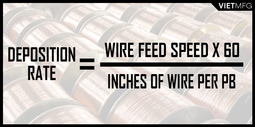
Deposition Rate is calculated as follows: take the wire feed speed, multiply with 60, and divide by its “inches of wire per lb”.
Deposition Rate = Wire Feed Speed (inch/min) x 60 min/hr / Inches of wire per lb (inch/lbs)
Understanding Deposition Rate will help you determine the wire feed speed to achieve a desirable current amount.
To achieve the same current level, smaller diameter wires require HIGHER wire feed speed than that of larger diameter wires.
For example, to reach 600 amperes, a 3/32 inch wire needs a wire feed speed of 150 ipm (inches per minute), while a 5/32 inch wire only needs 45 ipm.
- Thus, the 3/32 inch wire will have a deposition rate of around 17.3 lbs/hr;
- While the deposition rate of the 5/32 inch wire is 14.7 lbs/hr.
- In short, the use of smaller wire (3/32 inch) results in greater deposition rate. This allows for faster travel speed and productivity enhancement.
One connection with the Current Density is that: when the electrode wire reaches its current density capacity, any additional wire feed speed will increase Deposition Rate without any rise in current.
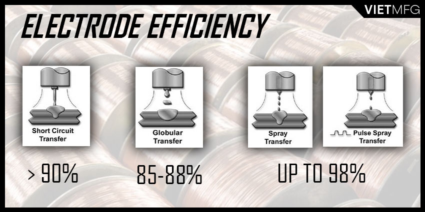
3. Electrode Efficiency
Electrode Efficiency shows the proportion (%) of electrode wire that is deposited into the molten weld puddle.
This numeric value is heavily influenced by the spatter level, slag former and smoke.
It is also a special parameter for each mode of metal transfer in MIG welding.
- For short-circuit transfer, electrode efficiency will range over 90%,depending on the amount of CO2 in the shielding gas mixture. The lower level of CO2 is, the higher the electrode efficiency becomes.
- For globular transfer, electrode efficiency varies from 85% to 88% with Pure CO2 as shielding gas. If Pure Argon is used, electrode efficiency ranges higher, from 88% to 90%.
- For axial spray transfer, electrode efficiency is very high, up to 98%.
- For pulsed spray transfer, electrode efficiency is also very high (up to 98%), but the requirement of high travel speed for this transfer mode may reduce electrode efficiency.
Conclusion
From this article, we hope you have found great information to help you understand more about the MIG wire, and how to select a proper wire for your MIG projects.
Reference
- Welding Principles and Practices (5th Edition) – McGraw Hill Education. Edward R.Bohnart. [2017]
- Gas Metal Arc Welding: Product and Procedure Selection – Lincoln Electric. [2014]
- How to Wire Feed Weld. Welding Headquarters. Retrieved September 28th 2020.
- MIG Welding Electrodes Wire Selection Guide. GoWelding. Retrieved September 30th 2020.
- Wire Feed Techniques and Tips. Youtube (Hoberts Welding Products channel). Retrieved September 30th 2020.


