MIG Welding Aluminum can be your worst nightmare, as it is very tricky and different from MIG Welding other metals.
In this article, we will show you in detail, how to MIG Welding Aluminum like a Pro:
We will cover the following content:
- What to prepare for MIG Welding Aluminum.
- Certain tips and tricks for enhancement of MIG Welding Aluminum.
Let’s dive right in!
When should you apply MIG Welding to Aluminum?
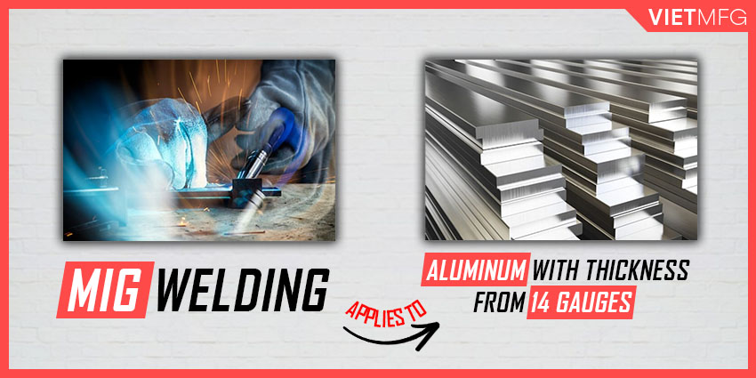
You should only apply MIG Welding to Aluminum when your aluminum thickness is around 14 gauges (5/64 inch).
For thinner aluminum, you can switch to TIG welding.
You should not attempt MIG Welding Aluminum on thinner workpieces because it can lead to burn through defects.
Why is MIG Welding Aluminum so difficult?
Aluminum is very challenging to MIG weld because:
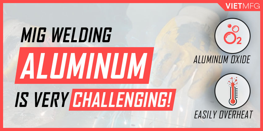
- Firstly, aluminum has an oxide layer located on its surface with a different melting point from the aluminum itself.
- Secondly, you cannot see a red hot weld puddle when MIG welding aluminum. This is why you can easily distort your workpiece from overheat.
Shielding Gas Selection for MIG Welding Aluminum
1. Shielding Gas Type
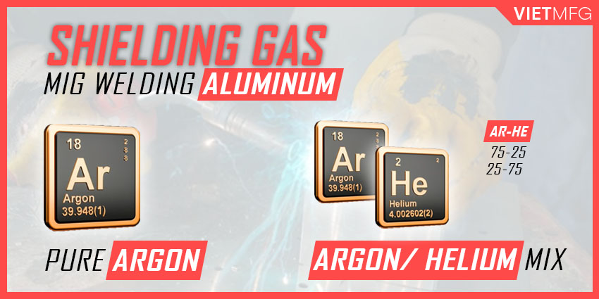
Pure Argon is the top MIG Welding Gas option of Aluminum.
This is applicable for Aluminum with thickness of up to 1/2 inch (12 mm).
If your material thickness exceeds 1/2 inch, you should switch to either 75% Argon + 25% Helium or 75% Helium + 25% Argon.
The addition of Helium in the arc provides greater energy which is dedicated for the thicker wall of aluminum.
2. Flow rate of Shielding Gas
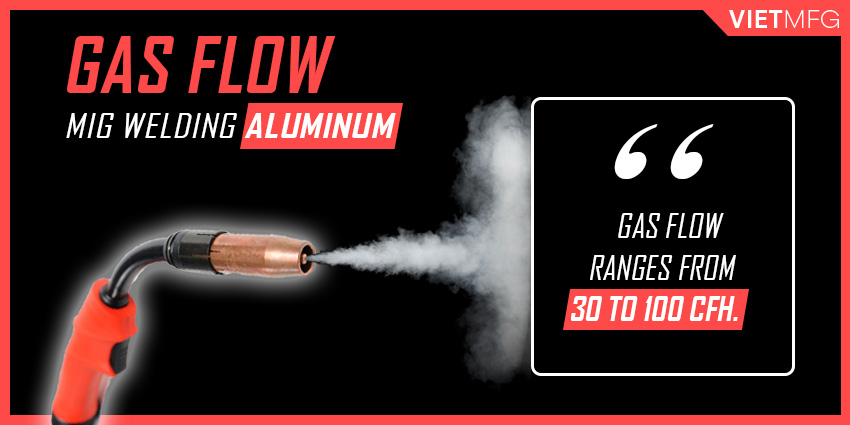
The flow rate of shielding gas must range from 30 to 100 cfh.
Higher flow rates often require a larger size of MIG Welding Nozzle, especially if the selected shielding gas is the helium two-part mixture.
3. Restricted Gas to use for MIG Welding Aluminum
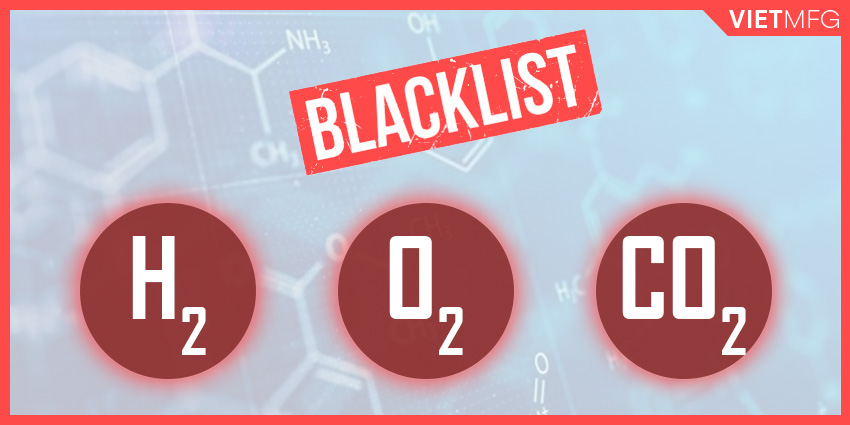
Shielding Gas whose components contain hydrogen, oxygen or carbon dioxide should be banned from application for MIG Welding Aluminum.
MIG Wire Selection for MIG Welding Aluminum
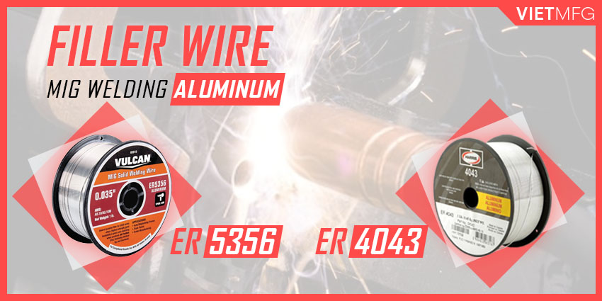
Top 2 options of Aluminum’s MIG Welding Wire Selection are ER4043 and ER5356 (if your weld requires more strength).
You can refer to our annex at the end of this article for a more detailed selection guide of filler wire.
However, for now, we can summarize the filler wire selection for MIG Welding Aluminum as follows:
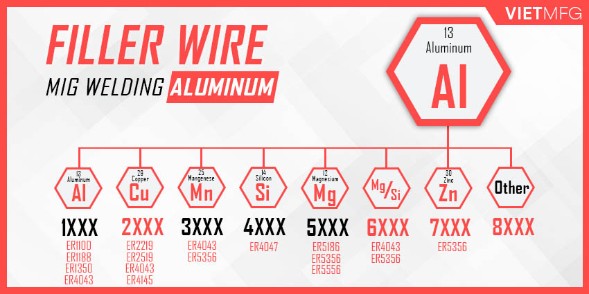
1. For 1XXX aluminum family
1XXX aluminum family is preferred for their high electrical conductivity and corrosion resistance.
Suitable filler metals for this family are ER1100, ER1188 and ER1350.
4043 filler wire is also acceptable, but produces lower electrical conductivity for the final weld.
2. For 2XXX aluminum family
2XXX aluminum family is not recommended for arc welding.
Some 2XXX alloys that are weldable include: 2219, 2014, 2519, 2008 and 2036.
Suitable filler metals for this family are ER2219, ER2519, ER4043 and ER4145.
5XXX filler wires MUST NOT be used to weld this aluminum family, as they can cause cracking.
3. For 3XXX aluminum family
3XXX aluminum family has high crack resistance.
Suitable filler wires for this family include ER4043 or ER5356 materials.
4. For 4XXX aluminum family
4XXX aluminum family usually works well with ER4047 filler metal.
5. For 5XXX aluminum family
For 5XXX aluminum family whose chemistry contains magnesium, it is recommended to use 5XXX filler metal with slightly higher magnesium content than that of the base metal.
Below are some suggestions for choosing filler wires for 5XXX aluminum family:
- 5052 base aluminum works well with ER5356 or ER5053 filler wires.
- 5454 base aluminum is suitable for ER5554 filler wires.
- 5083 and 5456 base aluminum are matched with ER5356, ER5186 or ER5556 filler wires.
6. For 6XXX aluminum family
For 6XXX aluminum family, it is advisable to use 4043 or 5356 filler wires to MIG weld.
7. For 7XXX aluminum family
For 7XXX aluminum family, only weld with 7005, 7003, and 7039 base aluminum.
You should use ER5356 as your filler wires.
Wire Drive System for MIG Welding Aluminum
As aluminum solid wire is very soft, a reliable wire drive system is very important to push the wire through a MIG torch.
Currently, there are 4 types of wire drive system (or feeder):
- Push Type Feeder.
- Push-pull Type Feeder.
- Special Push-pull MIG Torch for Aluminum.
- Spool Gun.
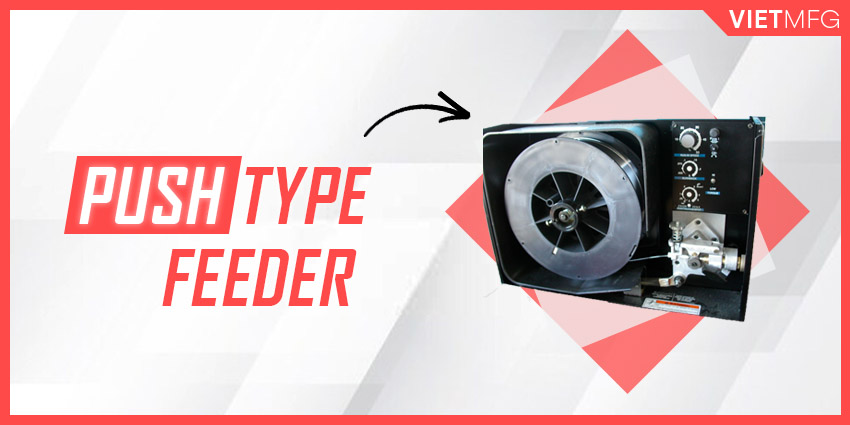
1. Push Type Feeder
In Push Type Feeder, a spool of filler wire is mounted to the rear of the drive roll assembly.
There is usually a set of drive rolls on the feeder which helps push the wire through to the contact tip.
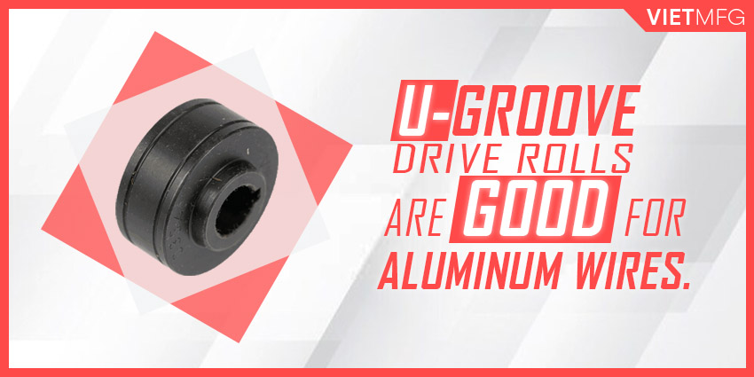
For aluminum wires, it is recommended to choose U-groove drive rolls.
Below are correct setup for Push Type Feeder:
- Keep the gun cable short (maximum 10 – 12 ft). The shorter the MIG gun cable, the better the overall performance.
- Depending on the wire diameter, choose a suitable filler wire that can be pushed. For example, ER4043 or ER5356 goes with 1/16 inch diameter.
2. Push-pull Type Feeder
For filler wires with small diameters (less than 1/16 inch), you should use a Push-pull Type Feeder.
This feeder combines a push motor located in the cabinet which holds the wire spool with a pull motor which handles the welding gun.
The latter motor (which handles the gun) controls the wire feed speed.
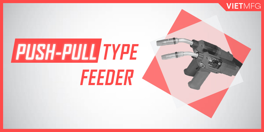
This wire drive system usually deals with aluminum diameters from 0.030 inch to 1/16 inch (0.8 – 1.6 mm) and can feed up to 50 ft of aluminum wires from the control cabinet.
3. Special Push-pull MIG Torch for Aluminum
Some push-pull type feeders are innovated to become a special version, which allows for better aluminum wire feed.
The motor handling the gun has variable torque with constant speed.
This permits the application of wire feed speed control.
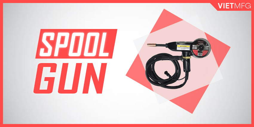
4. Spool Guns
Another solution for running soft aluminum wire is to use a spool gun.
In this gun, a spool of filler wire is mounted directly on the rear area.
This allows for easier push because the distance is just a few inches past the drive rolls.
These guns are usually air-cooled, so they are not suitable for higher current applications.
Aluminum MIG Welding Settings Chart
The table below summarizes the MIG Welding Correct Parameters setup for MIG Welding Aluminum for spray arc transfer, based on the base metal thickness.
MIG Welding Aluminum is NOT recommended to use with short-circuit transfer.
Table 1 – Aluminum MIG Welding Settings Chart (Spray Arc Transfer).
| Base Metal Thickness | Wire Diameter | Wire Feed Speed Setup | Voltage Setup (**) | Amperage Setup | |
| inch | mm | mm | ipm | volt | ampere |
| 1/8’’ | 3.2 | 0.9 1.2 | 350 – 400 240 – 270 | 21 – 22 | 110 – 130 |
| 3/16’’ | 4.8 | 0.9 1.2 | 425 – 450 300 – 325 | 23 – 24 | 140 – 150 |
| 1/4’’ | 6.4 | 1.2 1.6 | 350 – 375 170 – 185 | 24 – 25 | 180 – 210 |
| 5/16’’ | 7.9 | 1.2 1.6 | 400 – 425 200 – 210 | 26 – 27 | 200 – 230 |
| 3/8’’ | 9.5 | 1.2 1.6 | 450 – 480 220 – 230 | 26 – 28 | 220 – 250 |
| 7/16’’ | 11.1 | 1.6 | 240 – 270 | 28 – 29 | 280 |
| 1/2’’+ | 12.7+ | 1.6 | 290 – 300 | 29 – 30 | 300 |
(*): Pure Argon as shielding gas
MIG Welding Aluminum Tips and Tricks
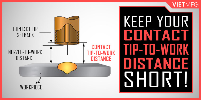
1. Keep your Contact Tip to Work Distance (CTWD) short
The most common error for MIG Welding Aluminum is to hold too long a Contact Tip to Work Distance.
Keep your CTWD shorter to about 1/2 inch to 5/8 inch (13 – 16 mm) is suitable for MIG Welding Aluminum.
Too long a CTWD will lead to insufficient shielding gas.
In that case, your MIG weld will turn gray.
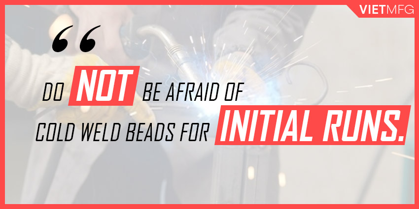
2. Do NOT be afraid of cold weld beads for initial welding runs
Do NOT freak out if at the start of your aluminum MIG welds, you get a cold weld bead for the first 1/2 inch (13 mm).
This is because of the high thermal conductivity of aluminum, as the heat is quickly drawn away from your weld.
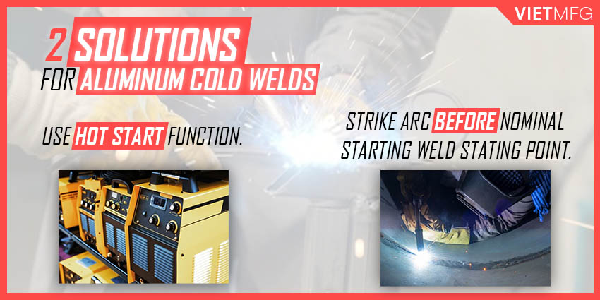
To solve this issue, you can use a power supply with a hot start.
One more solution is to strike the arc for about 1 inch (25 mm) ahead of the nominal weld starting point.
This can provide preheat to the aluminum base metal, and enhance fusion for your weld starting point.
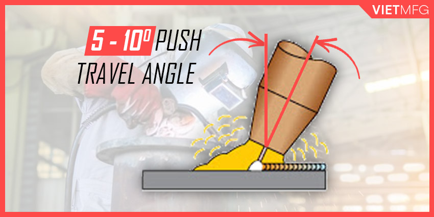
3. Use a push angle of 5 – 10 degrees
During your MIG welding process of aluminum, maintain your gun at a push angle of 5 – 10 degrees.
Do not use a drag angle (also known as a lagging angle), as it can lead to insufficient shielding gas for your weld puddle.
This will cause your finished weld turn black or gray.
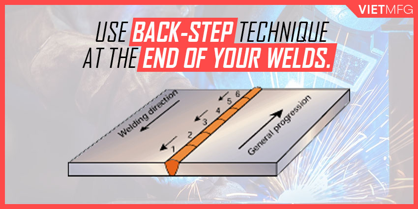
4. Do NOT stop your arc so abruptly!
Terminating your arc so abruptly will lead to deep weld crater.
Thus, near the end of your weld, intentionally increase the travel speed.
Then, reverse the direction of your gun to place the crater within the weld bead.
This is called “feathering” or “back step” technique.
This technique helps reduce the size of your weld bead and shrink the crater’s overall size.
Dictionary on the Selection of Electrode Wire for MIG Welding Aluminum
This section serves as a dictionary (or an annex) that you can always refer to whenever you have hard time selecting a proper electrode wire for your MIG Aluminum projects.
| Base Material | 319.0 333.0 354.0 355.0 380.0 | 356.0 357.0 359.0 413.0 444.0 443.0 | 511.0 512.0 513.0 514.0 | 7005 7039 710.0 711.0 712.0 | 6070 | 6061 6063 6101 6201 6151 6351 6951 | 5456 | 5454 | 5154 5254 | 5086 | 5083 | 5052 5652 | 5005 5050 | 3004 | 2219 2519 | 2014 2036 | 1100 3003 | 1060 1070 1080 1350 |
| 1060 1070 1080 1350 | 4145 | 4043 | 5356 | 5356 | 4043 | 4043 | 5356 | 4043 | 5356 | 5356 | 5356 | 4043 | 1100 | 4043 | 4145 | 4145 | 1100 | 1188 |
| 1100 3003 | 4145 | 4043 | 5356 | 5356 | 4043 | 4043 | 5356 | 4043 | 5356 | 5356 | 5356 | 4043 | 4043 | 4043 | 4145 | 4145 | 1100 | |
| 2014 2036 | 4145 | 4145 | 4145 | 4145 | 4145 | 4145 | ||||||||||||
| 2219 2519 | 4145 | 4145 | 4043 | 4043 | 4043 | 4043 | 4043 | 4043 | 4043 | 4043 | 4043 | 4043 | 4043 | 4043 | 2319 | |||
| 3004 | 4043 | 4043 | 5654 | 5356 | 4043 | 4043 | 5356 | 5654 | 5654 | 5356 | 5356 | 4043 | 4043 | 4043 | ||||
| 5005 5050 | 4043 | 4043 | 5654 | 5356 | 4043 | 4043 | 5356 | 5654 | 5654 | 5356 | 5356 | 4043 | 4043 | |||||
| 5052 5652 | 4043 | 4043 | 5654 | 5356 | 5356 | 5356 | 5356 | 5654 | 5654 | 5356 | 5356 | 5654 | ||||||
| 5083 | 5356 | 5356 | 5183 | 5356 | 5356 | 5183 | 5356 | 5356 | 5356 | 5183 | ||||||||
| 5086 | 5356 | 5356 | 5356 | 5356 | 5356 | 5356 | 5356 | 5356 | 5356 | |||||||||
| 5154 5254 | 4043 | 5654 | 5356 | 5356 | 5356 | 5356 | 5654 | 5654 | ||||||||||
| 5454 | 4043 | 4043 | 5654 | 5356 | 5356 | 5356 | 5356 | 5554 | ||||||||||
| 5456 | 5356 | 5356 | 5356 | 5356 | 5356 | 5356 | ||||||||||||
| 6061 6063 6101 6201 6151 6351 6951 | 4145 | 4043 | 5356 | 5356 | 4043 | 4043 | ||||||||||||
| 6070 | 4145 | 4043 | 5356 | 5356 | 4043 | |||||||||||||
| 7005 7039 710.0 711.0 712.0 | 4043 | 4043 | 5356 | 5356 | ||||||||||||||
| 511.0 512.0 513.0 514.0 | 4043 | 5356 | ||||||||||||||||
| 356.0 357.0 359.0 413.0 444.0 443.0 | 4145 | 4043 | ||||||||||||||||
| 319.0 333.0 354.0 355.0 380.0 | 4145 |
Source: AWS Specification A5.10
Conclusion
That is everything you need to know to perform MIG Welding Aluminum.
Mastering MIG Welding Aluminum is one of the toughest challenges for every fabricator.
Reference
- Welding Principles and Practices (5th Edition) – McGraw Hill Education. Edward R.Bohnart. [2017]
- Gas Metal Arc Welding: Product and Procedure Selection – Lincoln Electric. [2014]
- MIG Welding Gases. GoWelding. Retrieved September 28th 2020.
- MIG Welding Aluminum For Beginners. Make Money Welding. Retrieved October 5th 2020.
- How to Successfully MIG Weld Aluminum [Guide]. Miller. Retrieved October 5th 2020.
- How to MIG Weld Aluminum with a Spool Gun. Youtube (Miller Welders channel). Retrieved October 5th 2020.


