
Do you feel like you know all the basic definitions and theories about MIG welding, but still afraid to actually configure MIG welding Correct Parameters?
Well, this is because you have not got yourself familiar with all these things.
This article will give you just that, by offering you:
- 4 factors you must consider before choosing your MIG welder.
- A follow-along guide on how you set up everything for MIG welding.
This follow-along guide is a very exciting content. Thus, let’s kick things off right away!
FOUR things to consider when purchasing a MIG welder
1. Power requirement
The number one thing you need to think about is the power requirement of the welder.
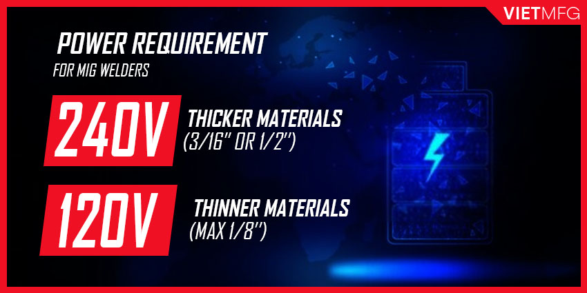
Nowadays, most welders offer 2 power options: 240V and 120V.
Machines with higher voltage will have higher amperage capability, and can perform MIG welding on thicker materials.
- If you are MIG welding thinner materials (thickness less than 1/8 inch), you should choose the 120V option.
- However, if you plan on MIG welding thicker materials (3/16 inch or 1/4 inch above), then go with 240V.
One notable thing is that 240V and 120V can have different names.
- Basically, 120V can also be called 110V or 115V.
- And you can hear other people say 220V or 230V; they are just other names of 240V.
Decide for yourself which option is most suitable for your business.
2. Base Material Thickness
The thickness of your base material will decide how much amperage you need to use from your welder.
Think about your business, which type of workpiece you will work on most often.
Are you going to work with sheet metal or plate, or other material types?
The answer to that question will suggest you choose an appropriate welder with the suitable amperage output.

3. Size of your working space
MIG Welders are usually compact and small in size.
However, some models are very large, which is dedicated to big MIG applications.
Thus, considering how large your working space is will help you select a more proper welder.

4. Your budget
Budget plays the most crucial role in your MIG welder selection decision.
Plan out your finance carefully.

How much are you willing to pay for equipment, including MIG welders?
Then, focus on choosing the machines in that price range.
Follow-along Guide on how to setup your MIG welding equipment
In this part, all you need to do is to follow along all the steps that we list out.
During this follow-along guide, we will add some tips and rules in MIG welding for you.
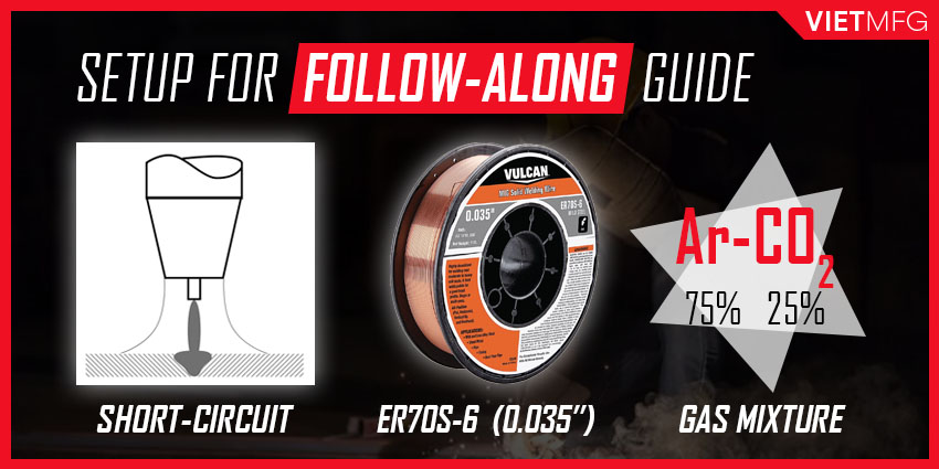
Please note that throughout this guide, we are:
- Doing a short-circuit MIG process.
- Using the O35 ER70S-6 wire type (diameter = 0.035 inch).
- Employing a 75% Argon + 25% Carbon Dioxide as the shielding gas.
And now, let’s start!
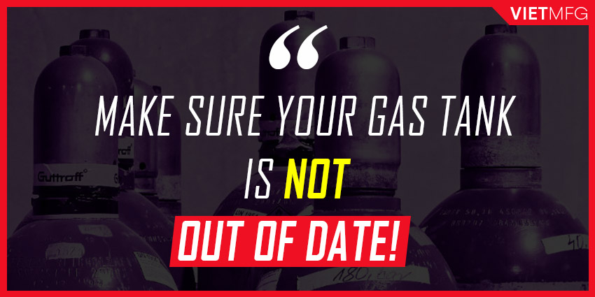
1. Preparing your MIG welding gas tank
Firstly, get yourself a shielding gas tank by contacting your local suppliers.
Get whatever size that fits your welding needs and budget.
Just make sure the stuff is NOT out of date.
2. Select the appropriate shielding gas
Please check out our article which focuses on MIG Welding Gas Selection.
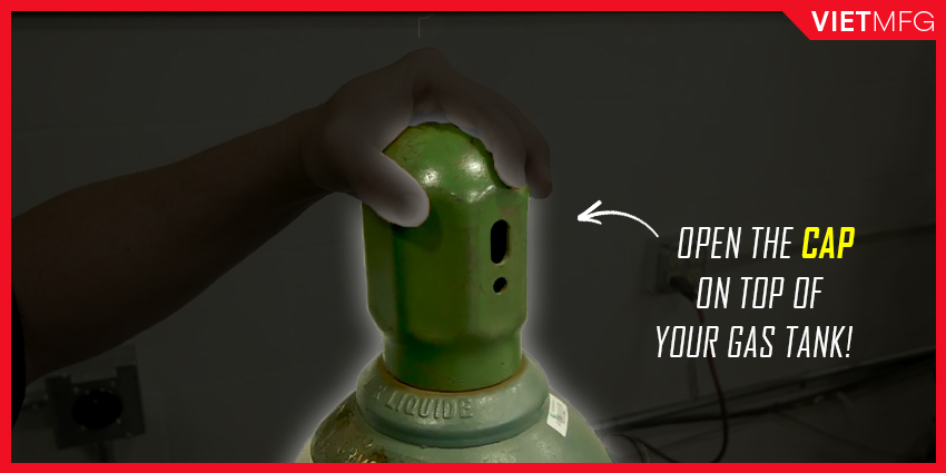
3. Open the cap on the top of your gas tank
Opening the cap located on the top of the gas tank is the first thing you want to do.
If you find it difficult to get this cap off, take a small hammer and just tap on the valve.
Do not need to beat on it.
Just tap it slightly, and the cap will twist right off.
After opening that cap, clean the tank neck area with a wire brush.
This will make it easier for you to get the cap on and off in the future.
Remember, do not put lubricants on this tank neck area, because they could create a fire hazard.
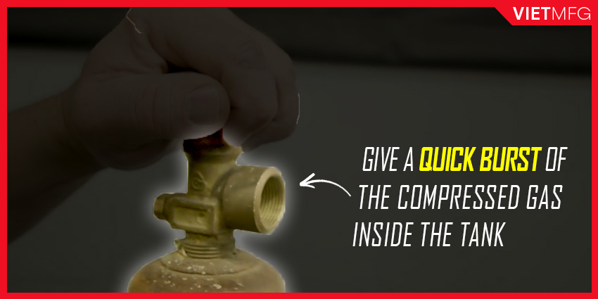
4. Give a quick gas burst
After getting the cap off, you should give a quick burst of the compressed gas inside the tank.
This is ONLY applied to non-flammable gases.
With flammable gases like acetylene or propane, you MUST NOT perform this action.
This quick burst helps blow out all the dust and debris located inside of the gas tank.
In many cases, the gas tank comes with a plastic cap on the valve that requires to be removed in the first place.
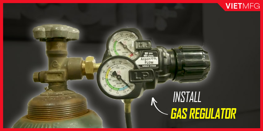
5. Install the gas regulator to the gas tank
After the quick burst, you can now install the gas regulator (flow meter) to the gas tank.
Make sure to use a wrench with appropriate size to tighten the brass nuts that connect the gas tank and the gas regulator.
6. Connect the shielding gas tank with the welder
When you finish installing the gas regulator, look for the hose of the gas tank.
Take the hose and attach it to the inlet of your welder.
Again, use the appropriate size wrench to tighten the outlet, which is the connection between the hose and the welder.
One tip is to use 2 wrenches: one for holding the inlet, the other for tightening the outlet.
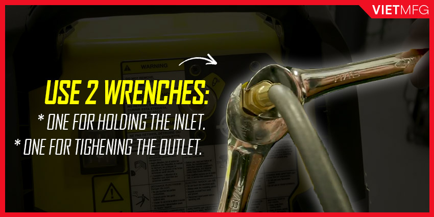
If you only twist the outlet, it will start unscrewing the inlet, which leads you to many problems later on.
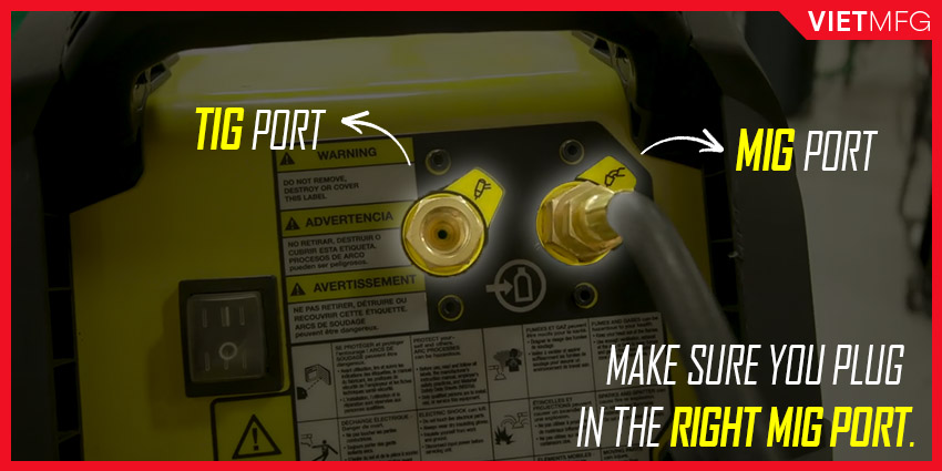
On the back of the machine, there are two different inlet options: one for MIG process, and the other for TIG process (illustrated via icon printed next to the inlet).
Make sure you plug the hose into the correct port.
Otherwise, it is not going to work.
7. Load your MIG wire onto the spool
Look for a small teat that sticks out on the inside part of the machine.
Then we have an opening on the wire spool.
Make sure to get that little teat line up this opening, so it will allow the machine to function properly.
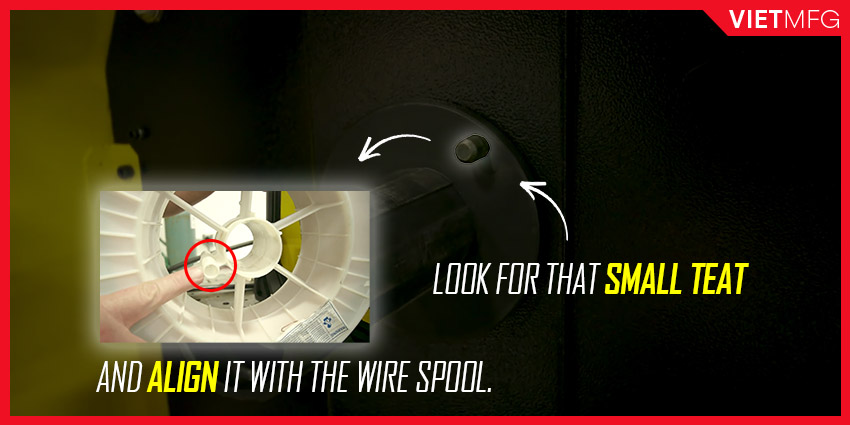
Moreover, the spool must be installed in a way that allows the MIG wire to travel in an anti-clockwise direction.
Such correct installation helps the wire enter the drive roll assembly and out to the MIG gun in a proper manner.
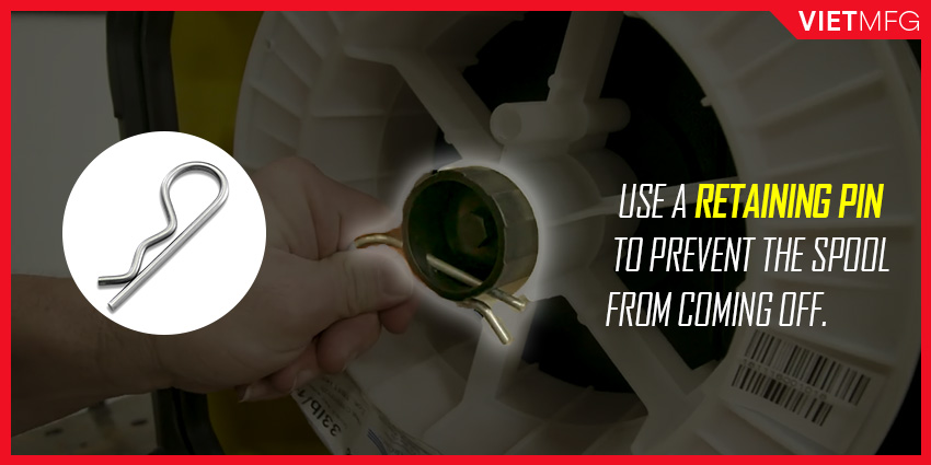
After loading the MIG wire onto the machine correctly, put a retaining pin on to prevent the spool from coming off during the MIG welding process.
8. Select the appropriate drive rolls
The drive roll assembly is located next to the wire spool inside the machine.
It acts as a bridge between the spool and the MIG gun.
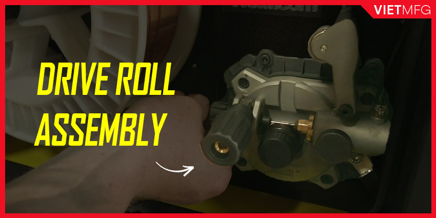
A drive roll assembly comprises 2 parts:
- The upper part contains a universal wheel and a pressure adjustment button.
- The lower part is where drive rolls stay.
Thus, a drive roll is a circular object with grooves (paths) carved along the circumference of the circle.
The paths are where the MIG wire runs over onto the MIG gun.
For that matter, the paths must match with the wire diameter.
A drive roll usually has 2 grooves with different sizes.
The size is printed on the opposite side of where the groove is.
In the following picture, you see the 0.035 mark there means the actual 0.035 inch groove is in the back side.
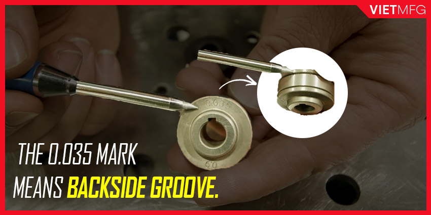
Why do manufacturers do it this way?
This is because when we put the drive roll onto the assembly, the groove in the back is the actual path that the MIG wire will travel on.
So, printing the size on the opposite side of the groove like that allows you to see the actual groove size being used.
A little bit discussion about Drive Rolls
There are 3 different designs of drive rolls:
- U-groove: is highly-polished and has a nice U contour; assures proper pressure on the wire without distortion; very suitable for soft aluminum wires.
- Knurled: has knurling inside; allows good gripping without too much pressure; suitable for both gas-shielded and self-shielded (flux-cored) applications; however produces feeding issues when used with solid wires.
- V-groove: is not as highly-polished and smooth as U-groove type, and does not have knurlings inside like the Knurled type; suitable for solid wires ranging from 0.015 inch to 0.0625 inch diameter.
Thus, in our case, we are using the V-groove Drive Rolls.
9. Set up the MIG wire through the drive roll assembly
The first part of your MIG wire is bended, and you cannot push it through the assembly.
So, make sure you clip it properly.
By properly, we mean that you must hold the wire with your LEFT hand, and clip it using your RIGHT hand.
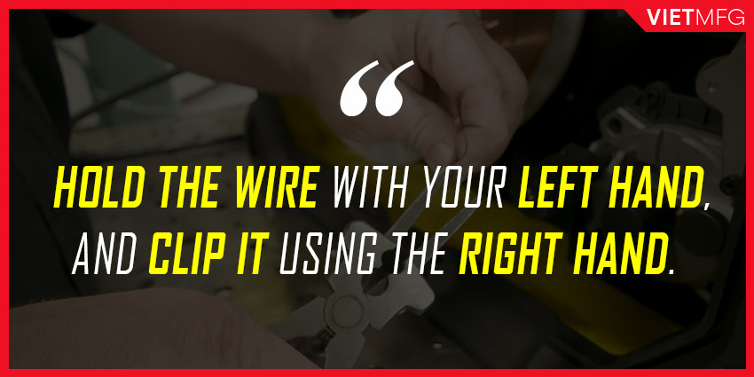
If you do it the reverse way, you will turn your wire spool into scrap metals.
Make sure you hold the part closest to the wheel and clip it off.
After clipping the part off, do not let go of the wire.
Continue to run it through the drive roll assembly.
Run about 6-8 inches passed outside.
It is just easier to line everything up this way.
10. Install the MIG wire to the MIG Gun
Next, grab the back end of your MIG gun, where there is a liner located.
The liner inside the gun must match with the wire diameter for the proper installation.
As we are using a 0.035 inch wire, so we should pick a liner that is suitable for that.
Put the MIG wire into the liner.
Then push the MIG gun towards the machine, and seal it tightly.
Make sure to put the MIG gun all the way in before sealing it off.
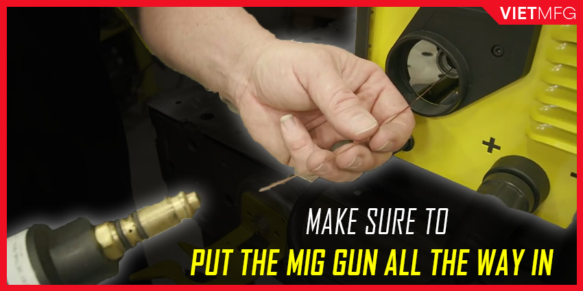
Otherwise, when you pull the trigger during the MIG welding section, you will hear shielding gas coming out right at the back end of the MIG gun.
This is because there are O rings right around these gas ports.
The MIG gun needs to be sealed tightly.
This creates a good airtight setup and helps all your shielding gas flows through the gun and out through the diffuser at the other end.
Tighten up the set of screws on the drive roll assembly to make sure the MIG gun cannot slide out and be locked in there relatively firm.
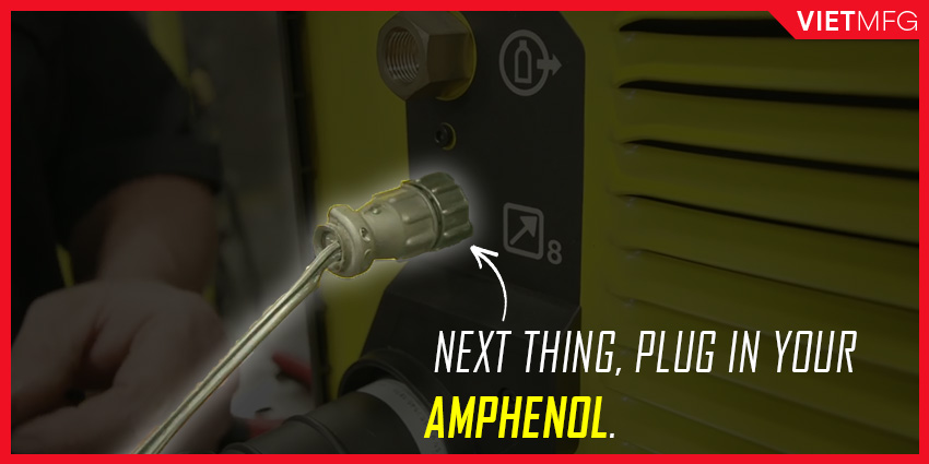
Next thing, plug in the Amphenol (power cable of MIG gun).
11. Stabilize the Spool
Stabilizing the spool means when you pull the trigger and you stop, the wire spool does not continuously spin.
So how do you stabilize the spool?
You can start off by loosening the spool, pull the trigger and stop, check whether the spool can stop on its own or not.
If not, slowly tighten up the spool and try again, until you get the desired result.
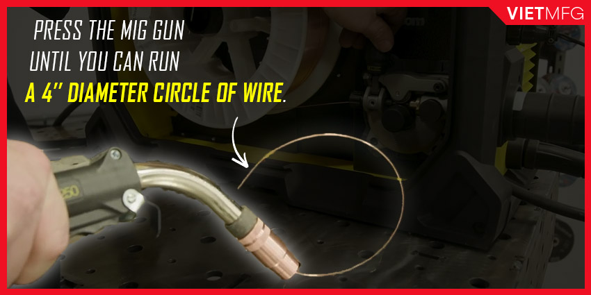
12. Put tension on your MIG wires
On the drive roll assembly, you need to put tension on the wire so that the drive roll will continuously push the wire during your MIG welding session.
Briefly speaking, we do not want too much tension on there, and we do not want not enough tension on there as well.
So how do you know that you have put enough tension on the wire?
Firsty, hold your MIG gun against the table which is not electrically connected to the system.
Then, loosen the pressure adjustment button to a point where your wire is not pushed out when you press the trigger.
After that, slowly tighten the button down until you can run a four-inch diameter circle of wire.
That sign suggests you have put enough tension on the wire.
Once you get to that point, stop and you are done with the tension setting.
13. Select the polarity
With MIG welding, we will run on DCEP, which stands for Direct Current Electrode Positive.
So, make sure you plug your drive roll assembly into the positive terminal.
Then, take the ground clamp, and connect it to the negative terminal.
We are done with polarity setup.
14. Turn the machine on!
Plug your machine into the appropriate power source.
Consult your local certified electrician about power requirements.
Make sure you have an adequate source of electricity coming from your home or your workplace.
You can use a “pigtail” to switch from 230V to 120V power sources.
Remember to only plug the machine in after you have done working with all the internal components of your welder.
Do not plug it in advance!
15. Setup your MIG gun
On the other end of your MIG gun, there is a nozzle and a contact tip.
MIG Gun Nozzle
The primary function of the nozzle is to direct shielding gas into the welding area.
We will talk about MIG Welding Nozzle more detailedly in another article.
Contact Tip
The contact tip is where your wire gets all the energy from.
It must match with your wire diameter.
If you try to do MIG Welding without a contact tip, or use an unsuitable one with your wire diameter, you will have varying, unstable amperages.
The contact tip gives you the most constant voltage and best amperage when you install it onto the MIG gun securely and tightly.
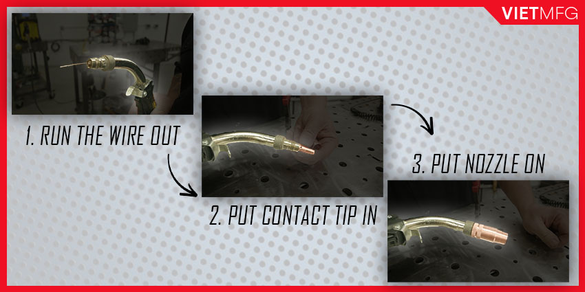
How to install Contact Tip and Nozzle?
Firstly, start running your MIG wire out.
Make sure your gas is turned off, because you do not want gas flowing as you’re trying to run your wire out.
Then, put the contact tip in, and put the nozzle on the whole thing.
Make sure your nozzle is clean by using some anti-spatter sprays.
A clean nozzle enhances your shielding gas flow.
16. Setup your shielding gas flow
Let’s go back to the valve on top of your gas tank for a while.
Adjust the gas flow to about 15-20 cfh, which is suitable for MIG short-circuit mode.
17. Setup parameters on your welder
For MIG welding, you need to care about 2 parameters on the welder: Wire Feed Speed and Voltage
Voltage for MIG Welding
As we all know by now, MIG welding is a constant voltage process.
That means if you set your voltage to 20V, you will get a constant 20V throughout your MIG welding session.
Voltage is the electro-motive force of current, which is similar to the pressure required to push that current, that amperage through the MIG gun.
The voltage amount will influence the size of your puddle:
- If you need a wider weld puddle, turn up your voltage.
- If you want a narrower weld puddle, turn down your voltage.
You just need to make sure you get enough voltage to push the amperage amount you have selected.
Wire Feed Speed for MIG Welding
Wire feed speed is going to be synonymous with the amperage.
This means the higher you turn your wire feed speed up, the more amperage you will get.
As you weld, your amperage will change significantly, depending on your contact-tip to work-distance (CTWD).
- If you pull back on your gun (longer CTWD), your amperage will decrease.
- If you push in further (shorter CTWD), your amperage will increase.
Remember, wire feed speed will control your heat.
- If you need more heat, turn up your wire feed speed.
- If you are having too much heat, turn down your wire feed speed.
You may also check the electrode manufacturer or the filler metal supplier to find out what settings they recommend.
Setting an appropriate amperage amount and wire feed speed depends on 2 main factors:
- Material thickness: Each 0.001 inch of material thickness requires 1 amperage of output. Thus, 0.125 inch = 125 amps.
- Wire size: Select one for your most commonly used thicknesses.
| Wire Size | Amperage Range | Wire Feed Speed Multiplier | Wire Feed Speed with material thickness of 0.125 inch |
| 0.023 inch | 30 – 130 amps | 3.5 inches per amp | 3.5 x 125 = 437.5 ipm |
| 0.030 inch | 40 – 145 amps | 2 inches per amp | 2 x 125 = 250 ipm |
| 0.035 inch | 50 – 180 amps | 1.6 inches per amp | 1.6 x 125 = 200 ipm |
| 0.045 inch | 75 – 250 amps | 1 inch per amp | 1 x 125 = 125 ipm |
18. Connect the ground clamp
It is recommended to put your ground clamp on the actual workpiece.
You will have better electrical connection this way.
However, it is fine to put the ground clamp on the table.
Conclusion
This is the end of the follow-along guide for setting up all your equipment for the MIG welding process.
It is time for you to apply welding techniques on the actual workpiece, to lay real beads on the metal.
By observing those beads, you can assess the quality of your MIG welding.
That is the topic of another article of ours.
Make sure to check it out, too!
Reference
- Welding Principles and Practices (5th Edition) – McGraw Hill Education. Edward R.Bohnart. [2017]
- Gas Metal Arc Welding: Product and Procedure Selection – Lincoln Electric. [2014]
- MIG Welding: Setting the Correct Parameters. Miller. Retrieved October 2nd 2020.
- Buying Your First MIG Welder. Youtube (Miller Welders channel). Retrieved October 2nd 2020.
- MIG Machine Setup for Beginners. Youtube (Weld.com channel). Retrieved October 3rd 2020.

