
MIG Modes of Metal Transfer are different ways of transferring the metal from filler wires to the weld puddle.
Depending on the setting you choose, you can find yourself in one of the FOUR modes.
In this article, we will discuss in detail exactly that, which are.
- Short-circuiting transfer.
- Globular transfer.
- Axial spray transfer.
- Pulsed spray transfer.
Let’s waste no time and start right now!
Short circuit MIG Welding
Short circuit MIG welding (GMAW-S) is the first mode of metal transfer.
Its name comes from the fact that the electrode wire touches the base metal and forms an electrical short-circuit.
This MIG welding process has other names: microwire welding, fine wire welding, and dip transfer.
The whole procedure of a short-circuit metal transfer is as follows:
- The electrical arc flows from the electrical wire to the workpiece, generating heat to melt both the base metal and the MIG wire.
- When the electrical wire meets the weld puddle, it produces short-circuits in the current flow and turns off the arc.
- To overcome the short-circuit, the amperage will increase significantly and form the arc again.
- This cycle of the arc turning on and off is repeated many times.
GMAW-S is the mode with low heat input, which is associated with low wire feed speed.
TWO important aspects of short-circuit transfer include:
- Wire diameter: Short-circuit metal transfer works well with MIG wires having diameter from 0.025 inch to 0.045 inch (0.6 – 1.1 mm).
- MIG Welding Gas Selection: Use Pure CO2 or a gas blend of 75% Argon + 25% CO2.
Short-circuit metal transfer works very well with sheet metal or thin materials.
The applicable material thickness ranges from 0.024 inch to 0.20 inch (0.6 – 5.0 mm).
Usually, short-circuit transfer comes with the following parameters:
- Voltage: set the value from 17 to 22 volts for most applications.
- Current: amperage level from 100 to 200 amperes only, which fits for welding thin base materials.
1. Advantages of Short-circuit MIG Welding
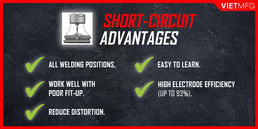
Short-circuit MIG Welding has the following advantages:
- Can be used for all welding positions, including overhead, horizontal, vertical-up and vertical-down.
- Work well even with poor fit-up conditions.
- Reduce welding distortion due to short-circuit nature of low heat input.
- Easier for operators to learn and apply.
- High electrode efficiencies, up to 93% (forget what electrode efficiencies are? Check it out at MIG Welding Wire Selection).
2. Disadvantages of Short-circuit MIG Welding
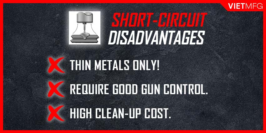
Short-circuit MIG Welding also has certain disadvantages:
- Limited application for thin metals only (sheet metal thickness, ranging from 0.025 inch to 0.045 inch).
- Requires operators to have a good control of the welding procedure (maintaining good gun position, setting correct parameters, etc.). If not, the result can be incomplete fusion, or excessive spatter.
- High cleanup cost after welding, due to excessive spatter mentioned above.
3. Inductance control of Short-circuit MIG Welding
Inductance is a feature dedicated for short-circuit MIG Welding that helps control the rate of current rise following the short-circuit condition.
In most cases, inductance can be fixed or variable, depending on the power source design.
- A fixed inductance is the optimum level of inductance built into the power source.
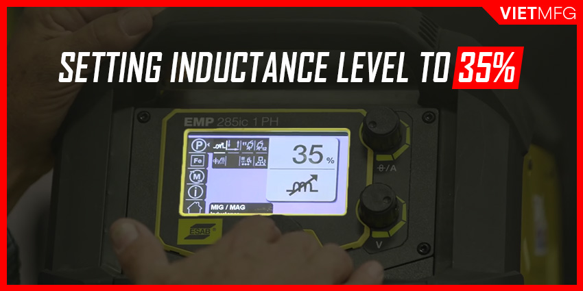
- A variable inductance indicates that the inductance level can be adjustable. The welder will have a knob button for you to change inductance level (measured in percentage).
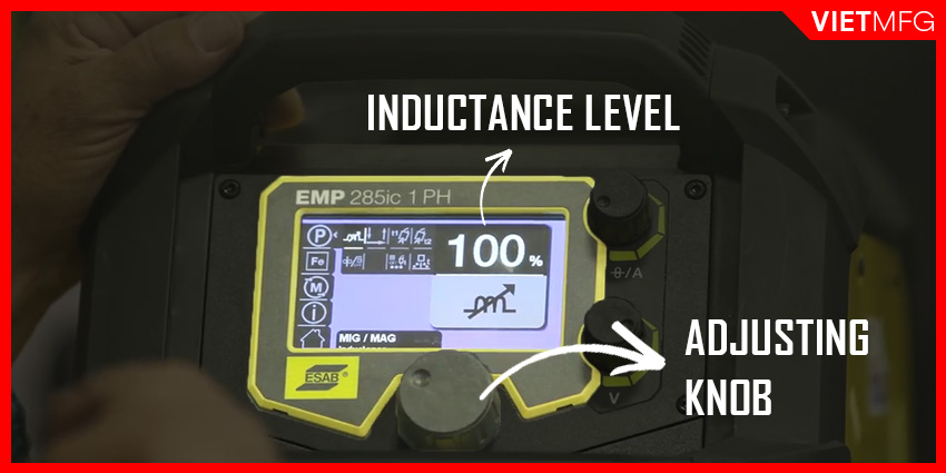
So, variable inductance allows MIG operators to increase or decrease the energy level to the short-circuit conditions.
Normally, setting the inductance level to 35% is a good start.
A more simple way to understand inductance is that it controls the frequency of droplet transfer per unit of time:
- INCREASING inductance level results in a DECREASE in the frequency of short-circuit metal transfer, and BIGGER droplet size.
- DECREASING inductance level results in an INCREASE in the frequency of short-circuit metal transfer, and SMALLER droplet size.
The ultimate goal of the variable inductance control feature is to transfer the smallest droplet possible to the puddle, with a sufficient energy amount and at the minimum level of spatter, to ensure good fusion.
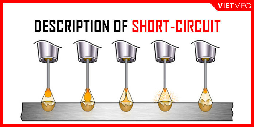
4. Description of Short-circuit MIG Welding
In Short-circuit transfer (SCT), the droplets are formed at the tip of the electrode.
However, instead of falling into the molten puddle, these droplets form a bridge between the puddle and the electrode (due to low wire feed speed).
This eventually creates a short circuit and generates the arc.
However, when the surface tension of the weld puddle pulls the molten metal bead off the electrode tip, everything is quickly reignited.
This process is repeated up to 200 times per second.
That is why with our bare eyes, we can clearly see a constant arc appear.
5. Cold Metal Transfer (CMT) – a variant of Short-circuit transfer
For MIG welding thin aluminum pieces, Cold Metal Transfer (CMT) is an ideal option.
Cold Metal Transfer is employed by lowering the current when a short circuit is formed.
This welding process is usually applied by robots.
It helps produce many drops per second.
Globular MIG Welding
Globular MIG Welding is another mode of metal transfer, which features a continuously fed solid wire electrode deposited into the weld puddle in a combination of short-circuits and gravity-assisted large droplets.
Globular transfer often takes place right after short-circuiting transfer ends.
You can easily notice when globular mode begins, by looking for some large and irregularly-shaped droplets that are larger than the wire diameter.
These weirdly-shaped droplets can fall in any direction: staying out of the welding path, or even moving upwards to the contact tip.
Due to these giant droplets falling into the puddle, Globular MIG Welding produces a severe spatter level and is much more difficult to control.
Globular transfer is suitable for the fabrication of sheet metal with thick thicknesses.
This mode of metal transfer works well with a binary blend of Argon and CO2 (or Pure CO2) as shielding gas.
1. Advantages of Globular MIG Welding
The application of Globular MIG Welding brings about the following advantages:
- Cost-effective use of CO2 shielding gas, as CO2 is not expensive.
- Allows MIG operators to weld at very high travel speeds (up to 250 ipm).
2. Disadvantages of Globular MIG Welding
However, Globular MIG Welding bears certain disadvantages as follows:
- Produce severe spatter levels, which boost the cleanup cost after welding.
- Make the welding control much more difficult for MIG operators.
- Lack of proper control can lead to incomplete fusion, which increases repair costs.
- Electrode efficiencies are reduced to around 87-93%, due to higher spatter level.
Axial Spray MIG Welding
Axial Spray MIG Welding features a continuously fed solid wire electrode deposited into the weld puddle at a higher energy level.
The effect of high energy levels results in a stream of small droplets.
Unlike Globular transfer, in Axial Spray MIG Welding, the droplet stream falls axially across the arc.
Axial Spray transfer takes place when MIG operators switch from Globular to Spray transition current.
You will know the occurrence of Axial Spray transfer by seeing a stream of metal droplets travelling axially from the end of the electrode wire.
Axial Spray MIG Welding can be applied for many common materials, including: MIG Welding mild steel, MIG Welding stainless steel, and other metals like magnesium, copper alloys, nickel alloys, etc. with thickness over 0.25 inch (6.4 mm).
Shielding gas employed in Axial Spray transfer includes the binary blends of Argon + O2 (where O2 level is under 5%), or Argon + CO2 (where CO2 level is less than 18%).
The final result of Axial Spray transfer is an excellent bead appearance.
However, to achieve such a positive result, the weld joints must be free of millscale, oil or dirt.
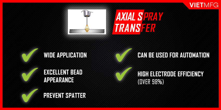
1. Advantages of Axial Spray MIG Welding
The application of Axial Spray MIG Welding has some advantages:
- Provide high deposition rates and high electrode efficiency (over 98%).
- Work well with a wide range of filler metal materials and various wire diameters.
- Create excellent weld bead appearance and weld fusion.
- Prevent spatter effectively, which leads to lower cleanup cost.
- Can be used in semiautomatic, hard automation or robotic applications.
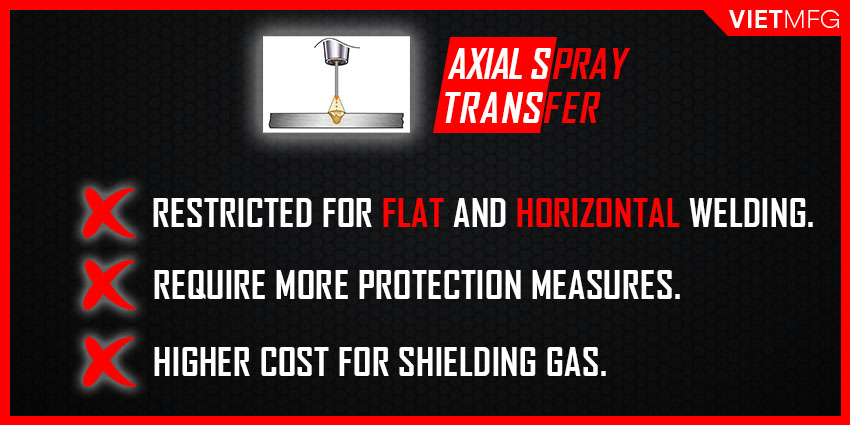
2. Disadvantages of Axial Spray MIG Welding
Here are some disadvantages of Axial Spray MIG Welding:
- Restricted to only 2 welding positions: flat and horizontal.
- Generates more welding fumes.
- Due to the nature of high energy level, Axial Spray transfer creates more radiated heat and extremely bright arc, which requires MIG operators to prepare more protection measures.
- Higher cost for shielding gas.
Pulsed Spray MIG Welding
Pulsed Spray MIG Welding (GMAW-P) is a variant of Axial Spray transfer, using pulsed current to melt the filler wire and allowing for one single droplet with each pulse.
In GMAW-P, pulsing current means the current continuously goes up and down and cycles between a high peak level to a low background level, and ranges from 30 – 400 pulses per second.
Thanks to the pulsing current, Pulsed Spray MIG Welding requires less heat input and creates no spatter (due to no formation of any short circuit).
The invention of Pulsed Spray MIG Welding is to solve 2 problems:
- Prevent the occurrence of weld spatter.
- Remove the incomplete fusion limitation, which is associated with Short-circuit and Globular transfers.
Pulsed Spray transfer is suitable for solid wire electrodes of various material types, with diameters ranging from 0.045 inch to 5/64 inch (1.1 – 2.0 mm).
A binary gas mixture of Argon + CO2 (with CO2 level under 18%) works well for Pulsed Spray transfer.
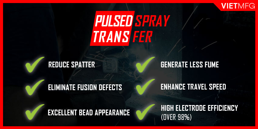
1. Advantages of Pulsed Spray MIG Welding
Pulsed Spray MIG Welding has the following advantages:
- Reduce significantly spatter level.
- Eliminate fusion defects that are associated with other MIG metal transfer.
- Produce excellent weld bead appearance.
- Generate less weld fume, compared to Axial Spray transfer.
- Capable of out-of-position welding.
- Handle poor fit-up effectively.
- Electrode efficiencies can reach up to 98%.
- Enhance welding travel speeds (around 200 ipm).
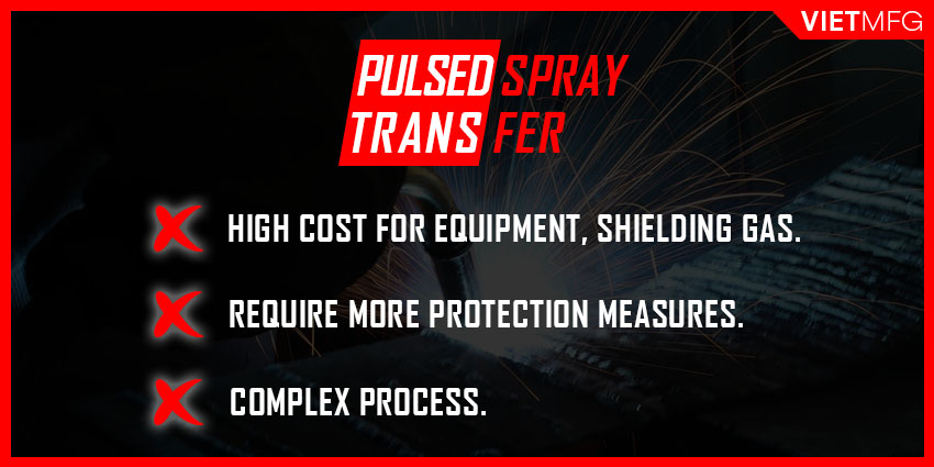
2. Disadvantages of Pulsed Spray MIG Welding
The use of Pulsed Spray MIG Welding also leads to certain limitations below:
- Higher cost for equipment to support this metal transfer process.
- Higher cost for shielding gas, due to the high level of Argon.
- Higher energy required for the process, which demands more protection measures.
- Quite a complex process for MIG operators to carry out.
Conclusion
That’s it! All 4 MIG modes of metal transfer in ONE single place for you.
We hope you find some interesting knowledge from this article.
Reference
- Welding Principles and Practices (5th Edition) – McGraw Hill Education. Edward R.Bohnart. [2017]
- Gas Metal Arc Welding: Product and Procedure Selection – Lincoln Electric. [2014]
- MIG Welding Transfer Types. GoWelding. Retrieved October 5th 2020.
- Modes of Metal Transfer | Short-circuit vs Spray vs Globular. Weld.com. Retrieved October 5th 2020.

